Method for connecting RFID antennas independent of slave mainboard

A connection method and motherboard technology, applied in the field of RFID antennas, can solve the problems of reduced product market competitiveness, reduced working speed and efficiency, longer working time, etc., to facilitate manufacturing work, improve speed and efficiency, and reduce occupied area. Effect

Pending Publication Date: 2021-03-26
中山市博安通通信技术有限公司
View PDF0 Cites 0 Cited by
  • Summary
  • Abstract
  • Description
  • Claims
  • Application Information

AI Technical Summary

Problems solved by technology

[0004] The purpose of the present invention is to provide a method for connecting an RFID antenna independent from the main board to solve the above-mentioned background technology. In the existing market, a differential circuit is added at the main board end to adjust the antenna state. The obvious disadvantage is that the RFID chip and the differential Circuits all occupy space resources on the motherboard side. For some products, the space on the motherboard side is very important, such as smart watches, smart bracelets and other products. This type of product itself is very crowded on the motherboard side, and a part of the area must be reserved for RFID. Antennas, this is even more difficult. It will not only increase the cost input during production work, but also increase the difficulty of the work, reduce the speed and efficiency of the work, and will also lead to a decrease in the market competitiveness of the processed products, resulting in the entire work. long time problem

Method used


Image

  • Method for connecting RFID antennas independent of slave mainboard
  • Method for connecting RFID antennas independent of slave mainboard
  • Method for connecting RFID antennas independent of slave mainboard

Examples


Embodiment 1

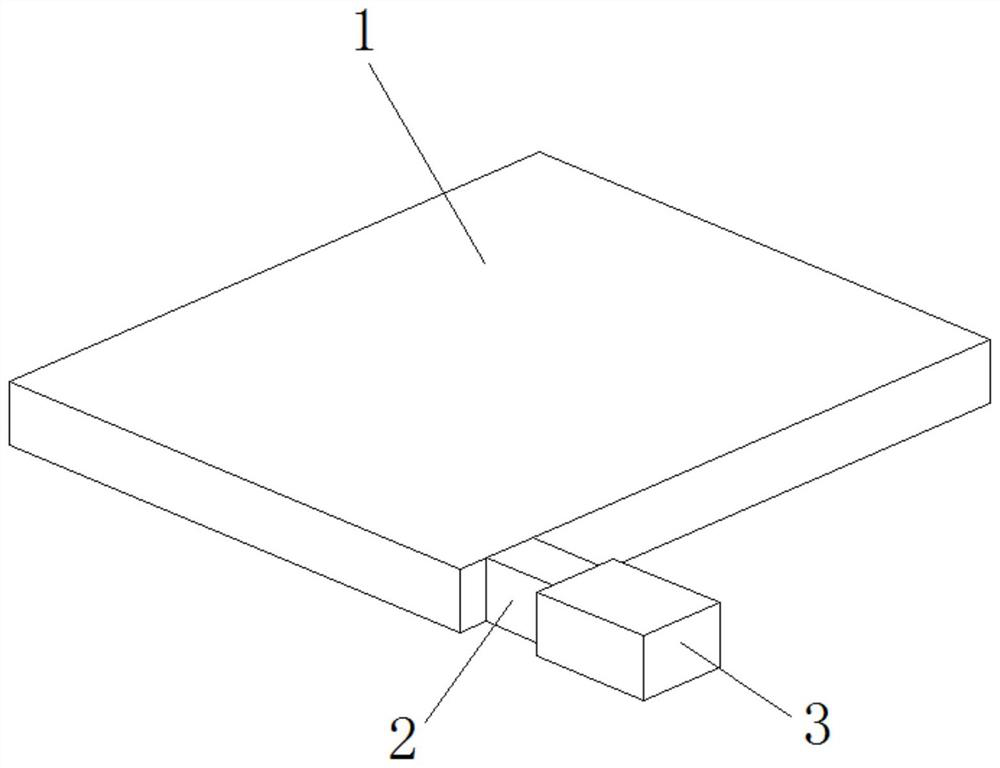
[0039] A method for connecting an RFID antenna independent from a motherboard, comprising the following steps:

[0040] Step 1: Debug and proof-roll the copper FPC coil according to the conventional thinking;

[0041] Step 2: Paste the RFID chip on the FPC, and the signal pin corresponds to one feedback pin of the coil;

[0042] Step 3: Connect and install through reserved matching, and use a large capacitor to control the frequency deviation of the resonance point.

Embodiment 2

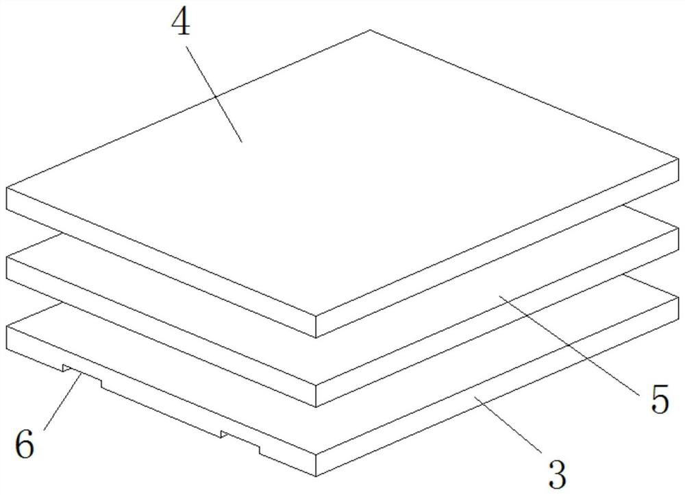
[0044] A method for connecting an RFID antenna independent from a motherboard, comprising the following steps:

[0045] Step 1: Debug and proof-roll the copper FPC coil according to the conventional thinking;

[0046] Step 2: Paste the RFID chip on the FPC, and the signal pin corresponds to the two feedback pins of the coil;

[0047] Step 3: Connect and install through reserved matching, and use a large capacitor to control the frequency deviation of the resonance point.

Embodiment 3

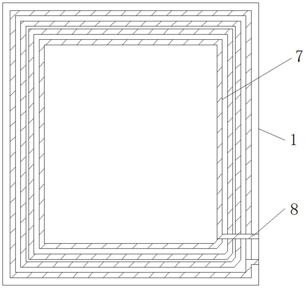
[0049] A method for connecting an RFID antenna independent from a motherboard, comprising the following steps:

[0050] Step 1: Debug and proof-roll the copper FPC coil according to the conventional thinking;

[0051] Step 2: Paste the RFID chip on the FPC, and the signal pin corresponds to the 3 feedback pins of the coil;

[0052] Step 3: Connect and install through reserved matching, and use a large capacitor to control the frequency deviation of the resonance point.


PUM


Abstract

The invention discloses a slave board independent RFID antenna connection method, and the method the following steps: 1, debugging and proofing a rolled copper FPC coil according to a conventional idea; 2, attaching an RFID chip to an FPC, allowing signal pins to be in one-to-one correspondence with feedback pins of the coil; 3, connecting and installing through reserved matching, and using a large capacitor to control frequency offset of a resonance point. An RFID antenna connecting structure independent from a main board comprises a product main board, a protective connecting end is fixedlyinstalled on the outer side of the product main board, an external connecting plate is movably installed at the protective connecting end, an RFID identification plate is fixedly installed at the upper end of a rolled copper FPC, and a positioning connecting groove is formed in the lower end of the external connecting plate. According to the method for connecting the RFID antenna independent fromthe main board, the installation convenience degree of a product is improved, the working difficulty is reduced, workers can conveniently conduct product manufacturing work, the machining and production speed is increased, and the cost input of product machining can also be helped to be reduced.

Description

technical field [0001] The invention relates to the technical field of RFID antennas, in particular to a method for connecting an RFID antenna independent from a motherboard. Background technique [0002] The principle of RFID is non-contact data communication between the reader and the tag to achieve the purpose of identifying the target. RFID is widely used. Typical applications include animal chips, car chip anti-theft devices, access control, parking lot control, and production line automation. , material management, non-contact two-way data communication through radio frequency, and use radio frequency to read and write recording media, so as to achieve the purpose of identification and data exchange. It is considered to be the information with the most development potential in the 21st century One of the technologies is to combine wireless communication with data access technology, and then connect to the database system to realize non-contact two-way communication, so...

Claims


Application Information

Patent Timeline
Patent Type & Authority Applications(China)
IPC IPC(8): G06K19/077
CPCG06K19/07756G06K19/07779
Inventor 谭海关宁
Owner 中山市博安通通信技术有限公司
Why Eureka
Try Eureka