
GPS-based vehicle warning and location system & method

a technology of location system and vehicle, applied in direction finders using radio waves, navigation instruments, instruments, etc., can solve problems such as lack of warning, driver turning off radar detector out of frustration, emergency vehicle and/or other vehicles

Inactive Publication Date: 2005-09-01
KING BYRON +1
View PDF18 Cites 74 Cited by
  • Summary
  • Abstract
  • Description
  • Claims
  • Application Information

AI Technical Summary

Benefits of technology

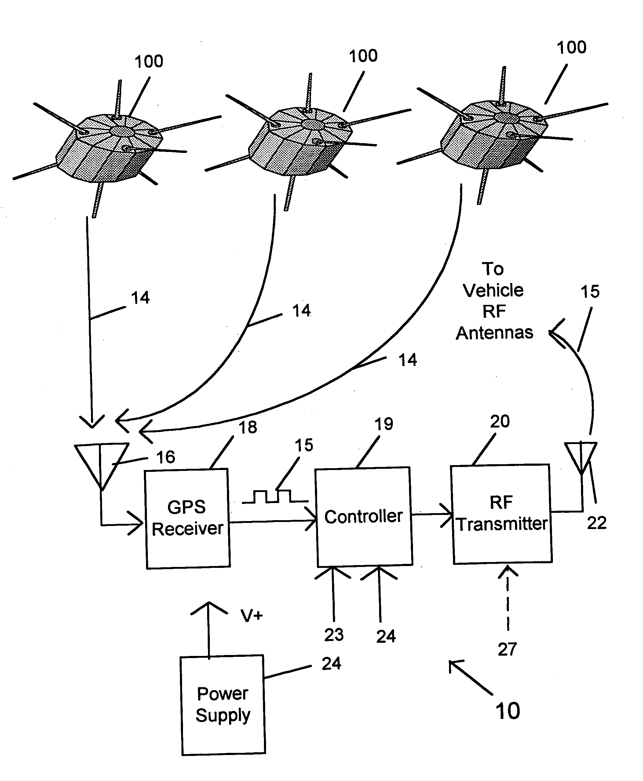
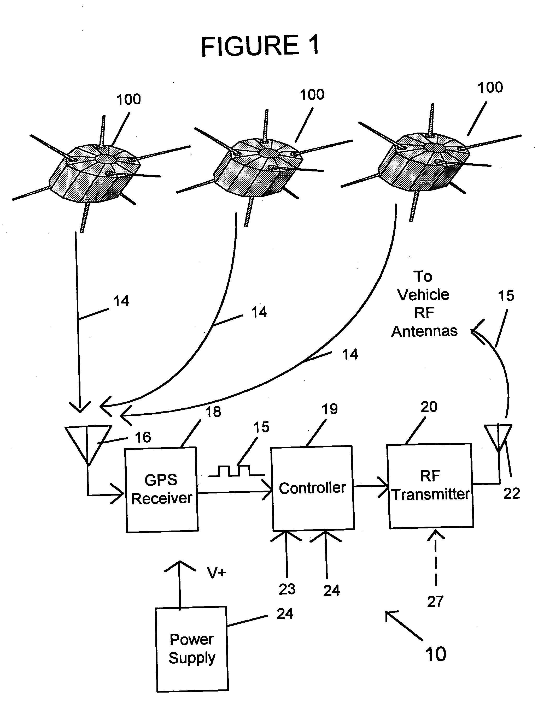
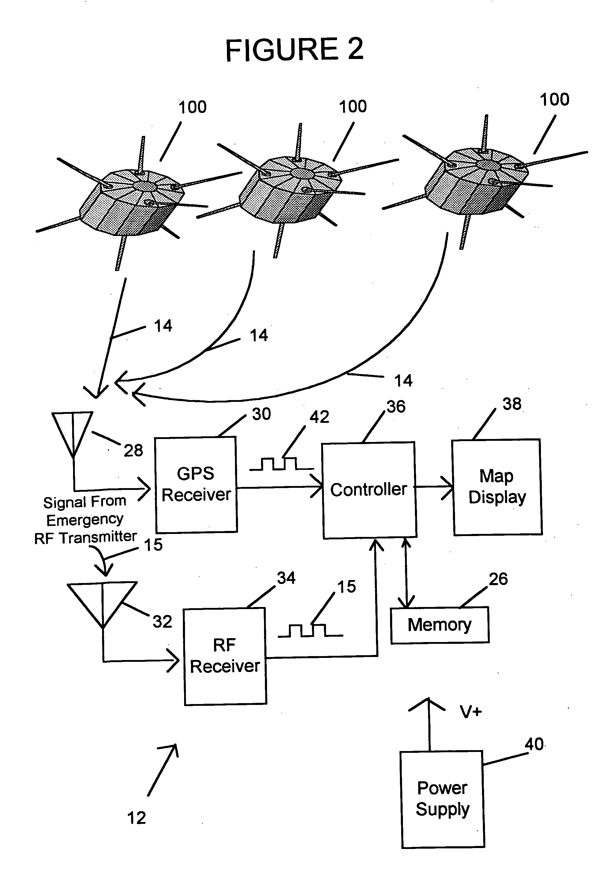
"The invention is an emergency vehicle alert system that allows a motor vehicle to receive information about an emergency vehicle's location. The system includes a GPS receiving unit on the emergency vehicle that receives GPS signals from multiple satellites and determines the vehicle's location. The system also includes a radio-wave transmitter on the emergency vehicle that sends a signal with the vehicle's location information. The system includes a GPS receiving unit on the motor vehicle that receives the emergency vehicle's location information and displays it on a map with other street locations. The technical effect of this invention is to provide a more efficient and effective way to alert motor vehicles about an emergency situation and allow them to react to it in a timely manner."

Problems solved by technology

When this occurs, it may result in a dangerous situation when the emergency vehicle approaches the unaware driver, which may result in the driver causing an accident with the emergency vehicle or with another nearby vehicle on the road.
Again, some drivers may not be aware of the sirens and emergency lights of the emergency vehicle, and this may result in an accident occurring with the emergency vehicle and / or other vehicles at or near the intersection.
One drawback to this solution is the lack of warning when an emergency vehicle is coming from behind a motor vehicle.
One drawing to this solution is that false triggering of the radar may result in a driver turning off the radar detector out of frustration.
Furthermore, the location and distance of the emergency vehicle would not be made available to the driver with this solution.
However, even with the Arbinger et al. solution, a driver is not provided precise information as to the exact location of the emergency vehicle, and so the driver may not choose the best streets to travel through in order to evade the emergency vehicle and to evade the snarled traffic that typically occurs on streets that the emergency vehicle travels on.

Method used


Image

  • GPS-based vehicle warning and location system & method
  • GPS-based vehicle warning and location system & method
  • GPS-based vehicle warning and location system & method

Examples


first embodiment

[0029]FIG. 3 shows a map display 300 that is displayed on the warning display 38 according to the invention, whereby the map display 300 provides, to a driver of the motor vehicle unit 12, both the precise position of the emergency vehicle unit 10 and the precise position of the motor vehicle unit 12. The map display is a street map showing the street that the motor vehicle unit 12 is currently located, as well as the surrounding streets within a particular range. For example, the map display 300 may include a map of streets that are within a 3 mile radius of a point from where the motor vehicle unit 12 is currently located. The map display 300 preferably has a feature in which it can be zoomed in or zoomed out by operator control, so that the driver can get a better perspective as to the location of his / her motor vehicle unit 12 and the emergency vehicle unit 10, with respect to a particular region.

[0030]FIG. 4 shows a map display 400 that is displayed on the warning display 38 acc...

third embodiment

[0033] In the invention, the emergency location signal string 15 is output from one or more stationary locations that do not correspond to motor vehicles. For example, in the morning and in the afternoon when school children are walking to or from a school, a school crosswalk will have an RF transmitter that broadcasts its precise latitude and longitude information, so that motor vehicles can stay clear of this zone or approach the zone with caution while children are walking on the street to and from the school. A similar feature can be utilized at a railroad crossing, and at locations (e.g., fire stations) where emergency vehicles enter traffic from their station locations, and at work zones on roadways in order to give drivers information regarding the presence of workers and equipment on or near a road that the driver is either on or close to. The same would apply to rail maintenance workers, and crosswalks for handicapped individuals at designated crosswalks. This would allow a...

fifth embodiment

[0043] In another possible implementation of the fifth embodiment, the map display will provide a greater level of visual highlighting of the street or path that coincides with the path or the intersection point of the path of the receiving vehicle. The “red line” feature described above may be used to provide for an extra level of highlighting on the map display when the emergency vehicle is determined to be very close to the motor vehicle, irrespective as to whether not the emergency vehicle and the motor vehicle are on the same road. For example, the emergency vehicle icon will be highlighted in red, and will flash on the map display, when the emergency vehicle is determined to be within ¼ of a mile of the motor vehicle.

[0044] Also, in an alternative configuration of the fifth embodiment, an audible alarm is provided to the motor vehicle operator, which provides audible information (by way of a speech synthesizer and speaker, for example) as to where the emergency vehicle is curr...


PUM


Abstract

An emergency vehicle alert system for providing information as to a location of an emergency vehicle to a motor vehicle, includes a first GPS receiving unit that is provided on the emergency vehicle and that receives GPS signals from GPS satellites and that determines emergency vehicle location information of the emergency vehicle. The system also includes a radio-wave transmitter unit that is provided on the emergency vehicle and that transmits the emergency vehicle location information by way of an emergency vehicle location signal. The system further includes a second GPS receiving unit that is provided on the motor vehicle and that receives GPS signals from GPS satellites and that determines vehicle location information of the motor vehicle. The system also includes a radio-wave receiver unit that is provided on the motor vehicle and that receives the emergency location signal output by the radio-wave transmitter unit of the emergency vehicle. The system further includes a map display that displays, on a map that includes a plurality of street locations, a current location of the motor vehicle a current location of the emergency vehicle. The emergency vehicle is shown as an icon on the map, whereby the icon has a different visual characteristic depending on the position of the emergency vehicle with respect to the motor vehicle.

Description

RELATED APPLICATIONS [0001] This application is a Continuation of U.S. patent application Ser. No. 10 / 421,819, filed Apr. 24, 2003, which is a Continuation-In-Part (CIP) of U.S. patent application Ser. No. 10 / 347,364, filed Jan. 21, 2003, both of which are hereby incorporated by reference in their entireties.BACKGROUND OF THE INVENTION [0002] 1. Field of the Invention [0003] The present invention relates to a method and apparatus for providing GPS based vehicle warning and location information to a vehicle operator. [0004] 2. Description of the Related Art [0005] Emergency vehicles need to travel quickly and safely through traffic in order to get to a destination. Conventional emergency vehicles use either sirens or emergency lights, or both, in order to get to the destination quickly and safely. It is often the case that a driver who is on the same road or a nearby road as the emergency vehicle is not made aware of the emergency vehicle's presence. This may be the case when the dri...

Claims


Application Information

Patent Timeline
Patent Type & Authority Applications(United States)
IPC IPC(8): G01C21/26G01S19/48G08G1/0965
CPCG08G1/0965G01C21/26
Inventor KING, BYRONYANCEY, DREW A.
Owner KING BYRON
Learn More