Satellite multi-choice switch system

Active Publication Date: 2005-09-01
NXP BV
View PDF0 Cites 79 Cited by
  • Summary
  • Abstract
  • Description
  • Claims
  • Application Information

AI Technical Summary

Problems solved by technology

As a result, the DBS system 100 does not allow multiple STBs to operate on one coaxial cable from the satellite antenna 104 and LNB 106 combination because multiple STBs would not be able to coordinate switching the polarization of the LNB 106.
In home environment this is a drawback of DBS systems compared to, as an example, standard non-DBS cable systems.
Unfortunately, the DBS system 100 is not capable of allowing multiple STBs to connect to the LNB 106 and provide independent simultaneous channel reception by each individual STB.
Unfortunately, the approaches described in FIGS. 1, 2, and 3 are multi-cable approaches that are high cost and cumbersome to arrange in the typical home environment bec

Method used


Image

  • Satellite multi-choice switch system
  • Satellite multi-choice switch system
  • Satellite multi-choice switch system

Examples


Embodiment Construction

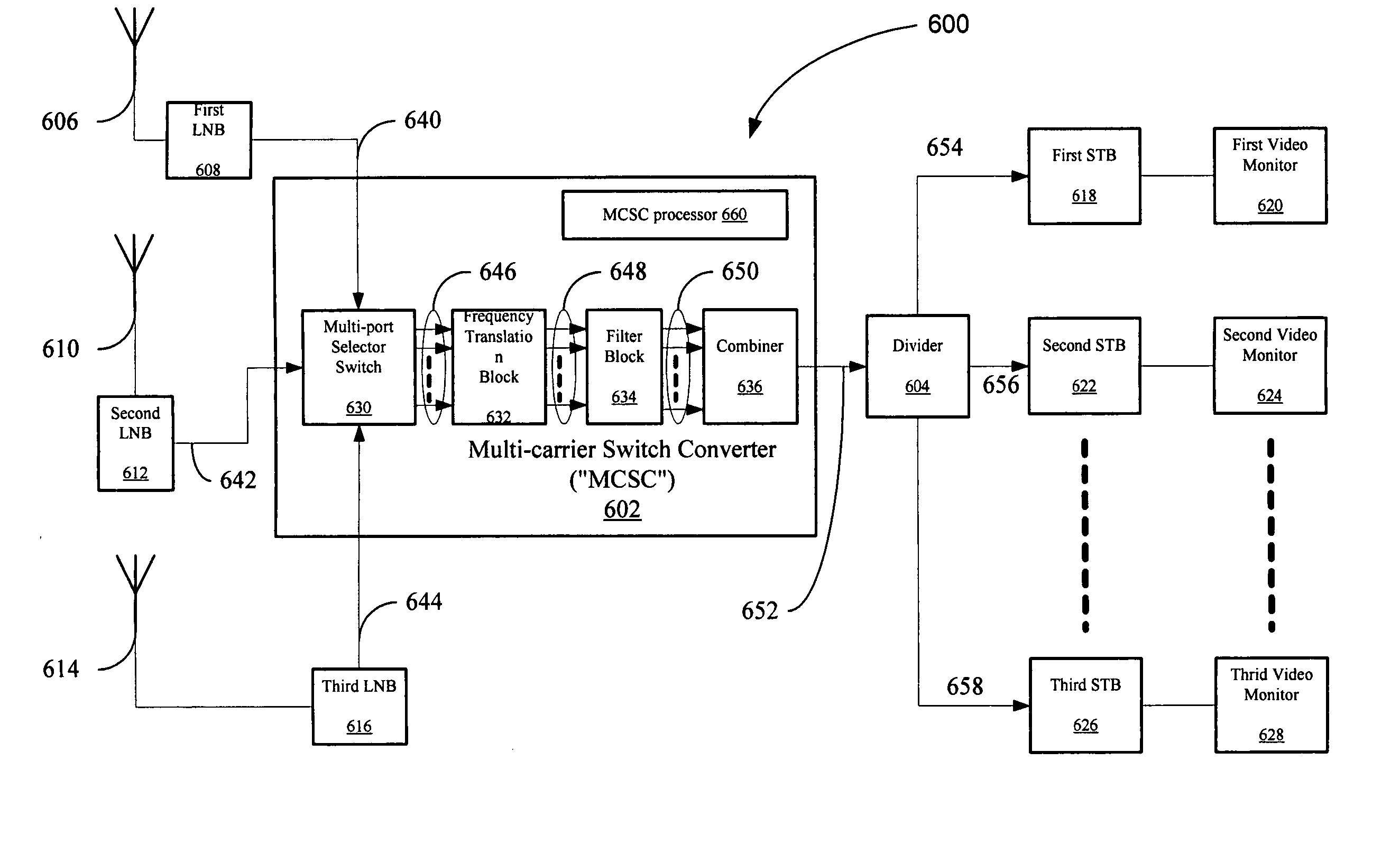
[0052] This invention discloses a Multi-carrier Switch Converter (“MCSC”). The MCSC is a system that allows several signals received from one or more satellite receiver LNBs in a DBS system to be combined and transported via a single cable to multiple satellite receiver tuner units, which are generally known as set-top boxes (“STB”). The MCSC frequency multiplexes the received satellite signals onto multiple carrier signals that may be combined into one combined signal where each carrier signal corresponds to a STB. As a result, the MCSC allows multiple video monitors to have access to several channels (from one or several satellites) simultaneously while at the same time reducing the number of required cables and other related equipment.

[0053] In general the MCSC operates by feeding the signals from several LNBs (after equalization) directly into a multi-port selector switch. The multi-port selector switch directs the signals to several mixers in several independent paths. The mix...


PUM


Abstract

A Multi-carrier Switch Converter (“MCSC”) for multiplexing a plurality of input signals received at the MCSC into a single MCSC output signal is disclosed. The MCSC may include a Multi-port Selector Switch, wherein the Multi-port Selector Switch receives the plurality of input signals and produces a Multi-port Selector Switch output, wherein the Multi-port Selector Switch output includes a plurality of switched output signals and a frequency translation block in signal communication with the Multi-port Selector Switch, wherein the frequency translation block receives the Multi-port Selector Switch output and frequency translates each switched output signal of the plurality of switched output signals to plurality of translated signals, wherein each translated signal has a fixed carrier frequency. Additionally, the MCSC may include a combiner in signal communication with frequency translation block, wherein the combiner receives the plurality of frequency translated signals and combines them to produce the single MCSC signal.

Description

CROSS REFERENCE TO EARLIER-FILED APPLICATIONS [0001] This application is continuation-in-part of U.S. patent application Ser. No. 10 / 611,400, titled “Satellite Transcoder,” filed Jun. 30, 2003, which is herein incorporated by reference in its entirety. [0002] This application claims priority under 35 U.S.C. Section 119(e) to U.S. Provisional Application Ser. No. 60 / 534,176 titled “Satellite Multi-Choice Switch System,” filed Dec. 31, 2003, and U.S. Provisional Application Ser. No. 60 / 590,025 titled “Satellite Multi-Choice Switch System,” filed Jul. 20, 2004, both of which applications are incorporated herein, in their entirety, by this reference.BACKGROUND OF THE INVENTION [0003] 1. Field of the Invention [0004] This invention relates generally to satellite communication systems. In particular, this invention relates to a switching system for distributing one or more satellite signals to multiple set-top boxes (“STB”). [0005] 2. Related Art [0006] From the inception of convenient di...

Claims


Application Information

Patent Timeline
IPC IPC(8): H04N7/20
CPCH04H40/90H04N7/20
Inventor LINDSTROM, MATSMOAZZAM, REZAMONIZ, JAMES
Owner NXP BV
Why Eureka
Try Eureka