
Rotatable carrier for objects or display

a technology for supporting objects and displays, applied in the direction of machine supports, revolving cabinets, furniture parts, etc., can solve the problems of not being easily seen by people, not suitably rotating, and display may not be clearly seen

Inactive Publication Date: 2005-09-08
KERNAN TECH
View PDF4 Cites 37 Cited by
  • Summary
  • Abstract
  • Description
  • Claims
  • Application Information

AI Technical Summary

Benefits of technology

"The present invention provides a rotatable carrier for supporting objects or displays in a way that they can be easily viewed from various angles. The carrier includes a casing, a detecting device, a rotating device, and an interacting member. The detecting device controls the rotating device to rotate the objects towards selected directions. The rotating device includes a gear, a motor, and reduction gearing. The casing includes a plate and balls for smooth support, and a control circuit for the motor. The housing also includes a center cavity and a peripheral flange for secure attachment to the casing. The interacting member blocks signals between the detecting device and the signal emitting device, and a switch or remote control device can be used for controlling the rotating device. Additional detecting devices can be attached to the casing to control the rotating means and prevent over rotation of the housing. The technical effects of the invention include improved viewing angles, smooth support, and secure attachment of the housing to the casing."

Problems solved by technology

Typically, various objects, such as displays, monitors, screens, etc. are stably or solidly supported on tables, and may not be suitably rotated relative to the tables, such that the objects or the displays may not be clearly seen by users from various directions or angles.
For example, in stock markets, the displays, or monitors, or screens, etc. are stably or solidly supported on tables or in cabinets and thus may not be easily seen by people.
However, the display, or monitor, or screen is conventionally and stably supported on tables, and may not be suitably rotated and directed to various people.

Method used


Image

  • Rotatable carrier for objects or display
  • Rotatable carrier for objects or display
  • Rotatable carrier for objects or display

Examples


Embodiment Construction

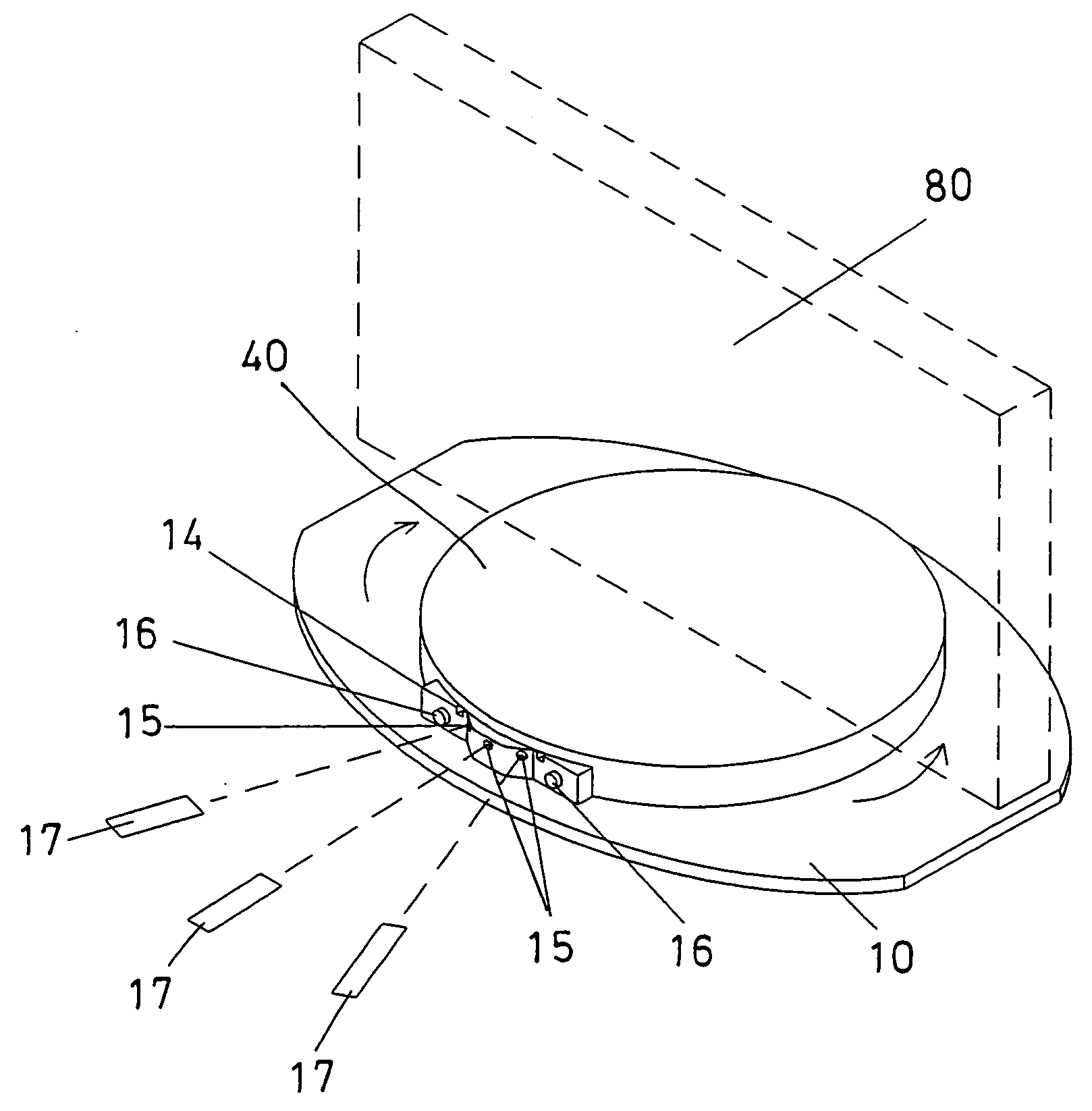
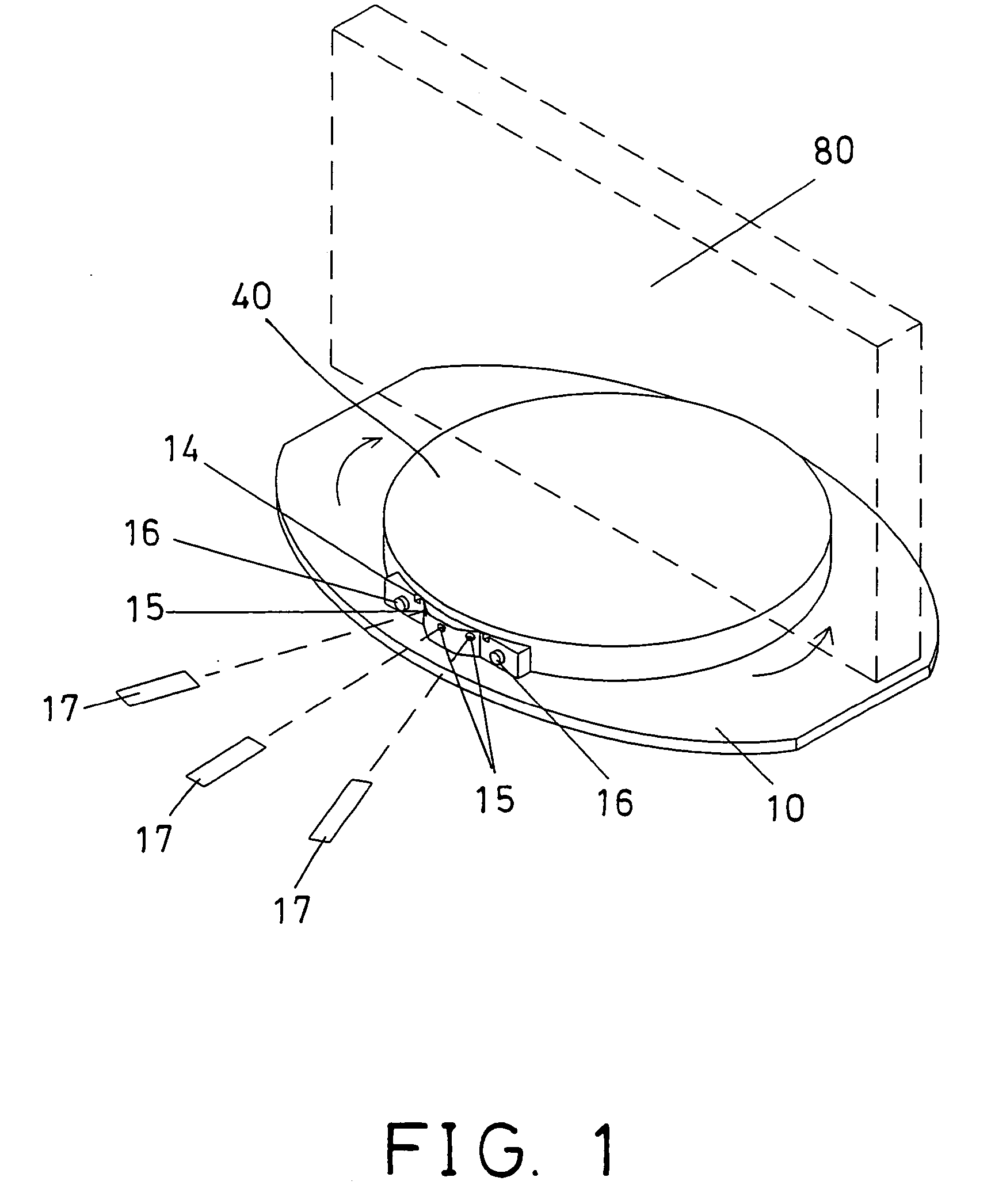
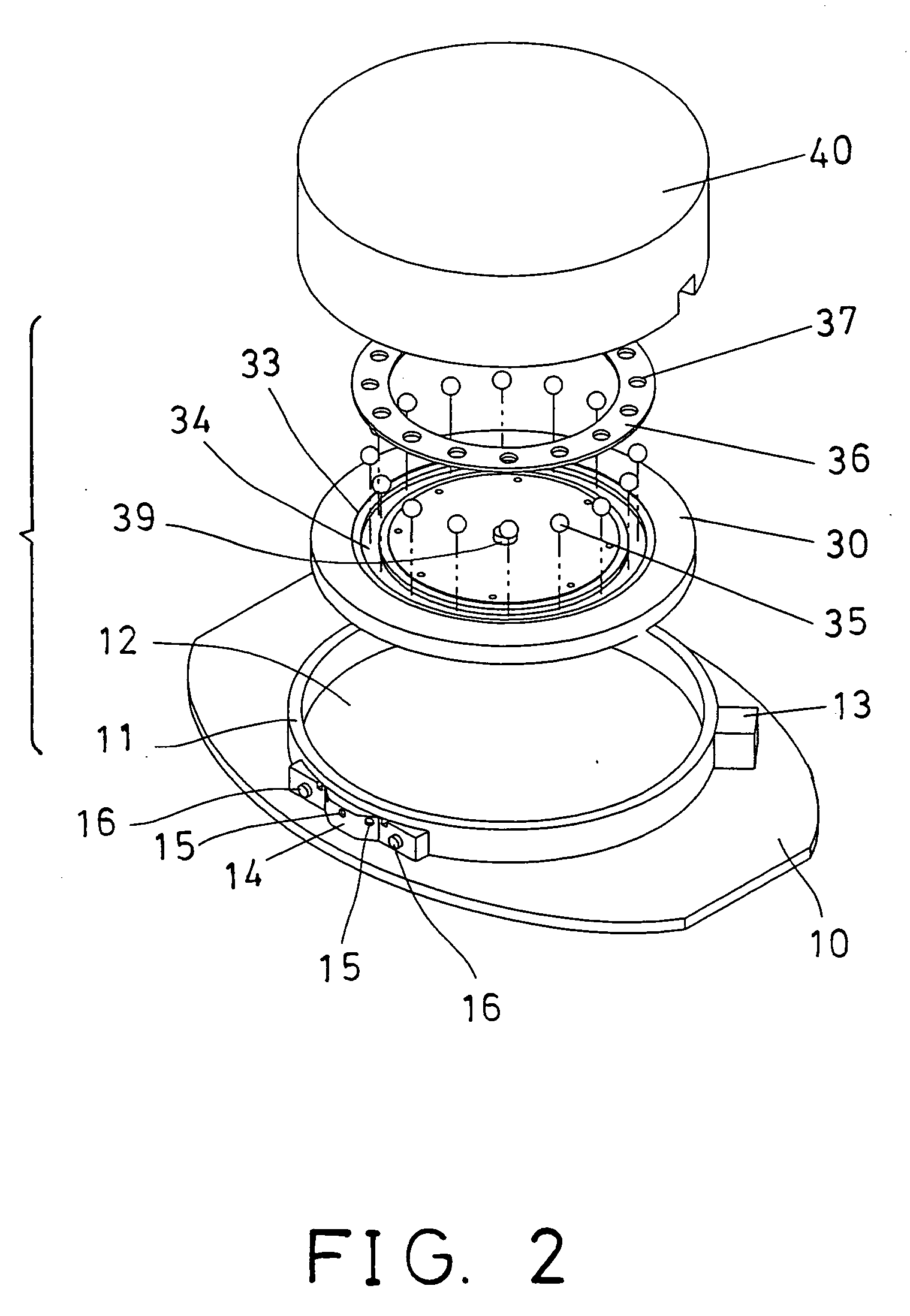
[0028] Referring to the drawings, and initially to FIGS. 1 and 2, a rotatable carrier in accordance with the present invention comprises a base 10 including a peripheral wall 11 extended therefrom to form or define a space 12 therein, and including a socket 13 attached thereto for coupling to electric power sources, and including a control device 14 attached thereto for controlling the rotatable carrier.

[0029] For example, the control device 14 of the rotatable carrier may include one or more signal receiver devices 15 directed toward various angles or directions, to suitably receive signals of remote control devices 17 from various angles or directions. The control device 14 may further include one or more switches 16 provided therein, for allowing the rotatable carrier to be controlled manually by the users.

[0030] As shown in FIGS. 4, 5, a casing 20 is received in the space 12 of the base 10, and secured to the base 10 with such as fasteners 21 (FIG. 5), and includes a periphera...


PUM


Abstract

A rotatable carrier includes a detecting device attached to a casing, a housing rotatably supported on the casing to support such as displays, and a rotating device for rotating the housing relative to the casing, to rotate the displays toward selected or suitable directions. The housing includes an interacting member arranged to act on the detecting device, and to control the rotating device, and to prevent the housing from being over rotated relative to the casing. The housing includes an inner rack, and the casing includes a rotatable gear engaged with the inner rack of the housing, and driven by a motor.

Description

BACKGROUND OF THE INVENTION [0001] 1. Field of the Invention [0002] The present invention relates to a rotatable carrier, and more particularly to a rotatable carrier for rotatably supporting objects or displays for allowing the objects or displays to be clearly seen from various directions or angles. [0003] 2. Description of the Prior Art [0004] Typically, various objects, such as displays, monitors, screens, etc. are stably or solidly supported on tables, and may not be suitably rotated relative to the tables, such that the objects or the displays may not be clearly seen by users from various directions or angles. [0005] For example, in stock markets, the displays, or monitors, or screens, etc. are stably or solidly supported on tables or in cabinets and thus may not be easily seen by people. [0006] In meeting, several people may have to watch a display, or monitor, or screen. However, the display, or monitor, or screen is conventionally and stably supported on tables, and may not...

Claims


Application Information

Patent Timeline
Patent Type & Authority Applications(United States)
IPC IPC(8): A47B91/00
CPCA47B49/00A47B49/008F16M11/18F16M11/08A47F5/025
Inventor TSAI, YUNG MINGCHUNG, KUO CHEN
Owner KERNAN TECH
Learn More