Micro-optics solar energy concentrator

a solar energy concentrator and micro-optic technology, applied in static indicating devices, instruments, lighting and heating apparatus, etc., can solve the problems of limiting the exact alignment required by the mirrored balls for concentrations much greater than 10, encumbring the use of solar energy, and high cost of photovoltaic solar cells

Inactive Publication Date: 2005-09-08
RABINOWITZ MARIO
View PDF3 Cites 16 Cited by
  • Summary
  • Abstract
  • Description
  • Claims
  • Application Information

AI Technical Summary

Benefits of technology

[0029] There are many aspects of this invention for single sheets that hold mirrored balls in solar concentrators and analogous

Problems solved by technology

The utilization of solar energy has been encumbered by the high cost of energy converters such as photovoltaic solar cells.
Another problem of the issued U.S. Pat. No. 6,612,705, is that of having higher friction than can be readily tolerated, which also

Method used


Image

  • Micro-optics solar energy concentrator
  • Micro-optics solar energy concentrator
  • Micro-optics solar energy concentrator

Examples


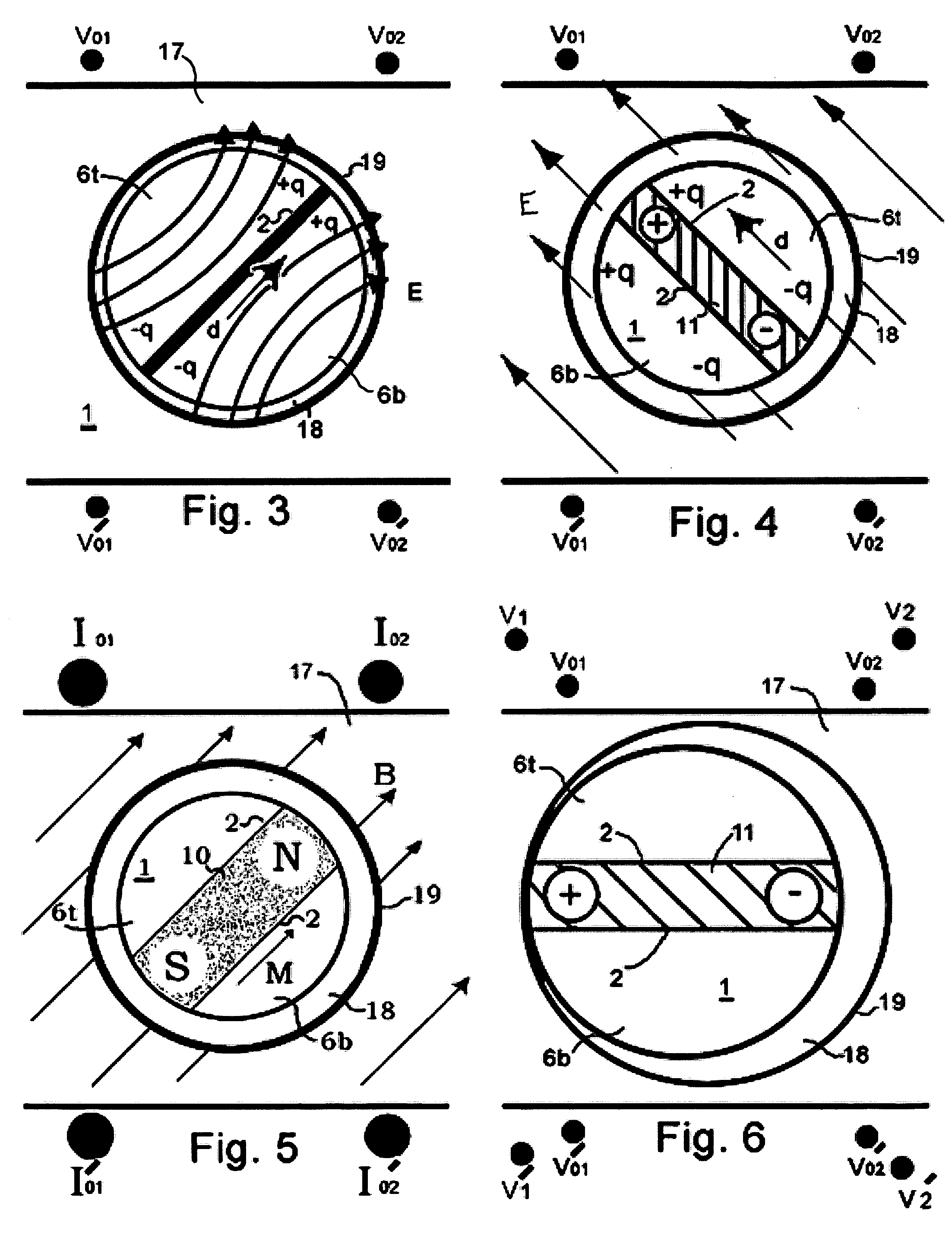
Embodiment Construction

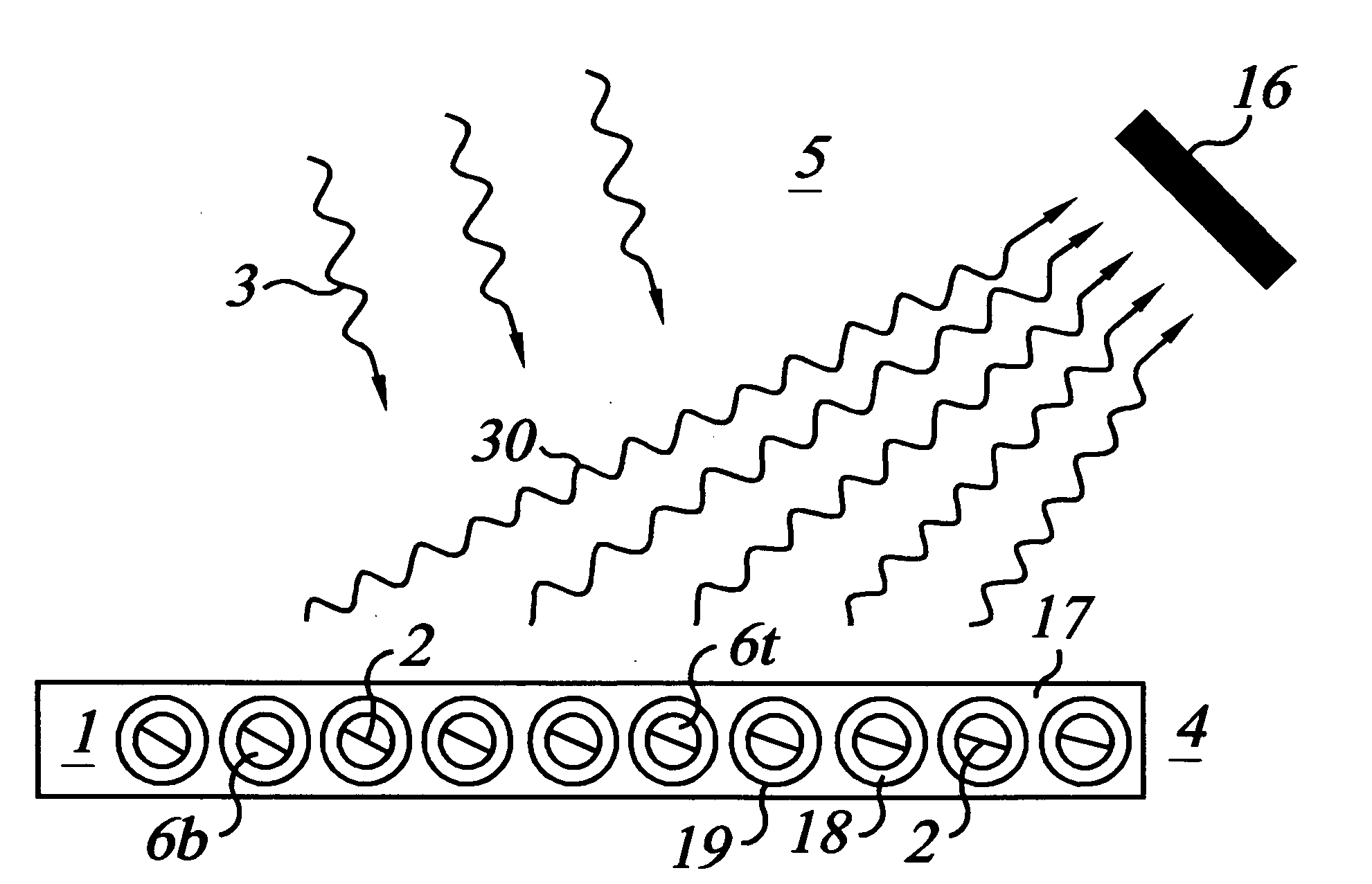
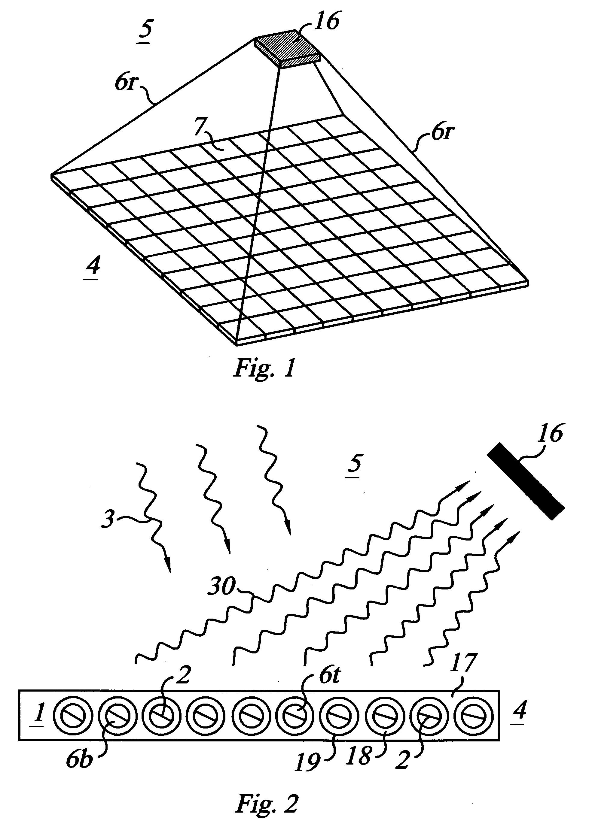
[0042]FIG. 1 is a perspective view of a pyramid configuration solar collection system 5 consisting of a micro-optics concentrator 4 and receiver 16 above it, supported by rods 6r. The micro-optics concentrator 4 may be a single large monolithic configuration, or as shown, it is preferably made up of separate modules 7 which are fastened together and secured to an existing surface such as the roof of a building or the ground. This facilitates installation, maintenance, and repair operations.

[0043] The pyramidal solar collection system 5 is a preferred embodiment when the concentration factor is roughly >10× and substantial forces of nature such as storms and earthquakes may be encountered. The receiver 16 is perched approximately above the center of the concentrator, with the rods making a roughly 45 degree angle with respect to the concentrator. This is an approximately desirable position and angle, but not critical.

[0044]FIG. 2 is a cross-sectional view of a solar collection syst...


PUM


Abstract

Novel method and apparatus are presented for coupling to a transparent sheet with an embedded array of preformed or formable mirrored micro-balls for use in a solar energy concentrator, and functionally similar applications such as optical switches and solar rocket assist. Mirrored micro-balls and particulate formable mirrors in cells are covered with a thin spherical shell of lubricating liquid so that they are free to rotate in an almost frictionless encapsulation in the sheet. Induced polarization electric or magnetic dipoles in the mirrors provide a novel method of controlling the alignment of the mirrored balls. Electrophoretically and magnetophoretically forming mirrors in situ on a rigid surface in a rotatable cell is also novel. Confining the balls and cells in cavities within a single sheet, rather than loosely between two sheets, allows for greater alignment accuracy which is needed for higher concentrations with gains greater than 10×. Immersing balls and cells in a lubricating fluid permits nearly frictionless rotation which reduces the power requirement for rotation, and further enables greater alignment accuracy as the impediment of unnecessary friction need not be overcome.

Description

INCORPORATION BY REFERENCE [0001] The following owned in common U.S. patents, allowed patent applications, and pending patent applications are fully incorporated herein by reference: [0002] U.S. Pat. No. 6,612,705, by Mark Davidson and Mario Rabinowitz, “Mini-Optics Solar Energy Concentrator” issued on Sep. 2, 2003. [0003] U.S. Pat. No. 6,698,693 by Mark Davidson and Mario Rabinowitz, “Solar Propulsion Assist” to issue on Mar. 2, 2004. [0004] U.S. Publication No. 2003-0202235-A1, by Mario Rabinowitz and Mark Davidson, “Dynamic Multi-Wavelength Switching Ensemble” allowed on Oct. 6, 2003. [0005] U.S. Publication No. Not Designated Yet, by Mario Rabinowitz, “Spinning Concentrator Enhanced Solar Energy Alternating Current Producton” is Pending. [0006] U.S. Publication No. Not Designated Yet, by Mario Rabinowitz, “Alignment of Solar Concentrator Micro-Mirrors” is Pending.BACKGROUND OF THE INVENTION [0007] This improved invention provides a better means to achieve low cost affordable sol...

Claims


Application Information

Patent Timeline
IPC IPC(8): G02B26/00G02B27/10
CPCF24J2/16Y02E10/40F24J2002/108F24J2002/1066F24S23/77F24S2023/85F24S2023/872
Inventor RABINOWITZ, MARIO
Owner RABINOWITZ MARIO
Why Eureka
Try Eureka