Lens, transmission screen, and method for manufacturing the lens

a transmission screen and lens technology, applied in the direction of mountings, magnification glasses, instruments, etc., can solve the problems of easy damage to the tip portion of the protrusion, difficult to meet the shape stability of the lens and the scratch resistance at high levels, and achieve the effect of high scratch resistan

Inactive Publication Date: 2005-09-08
ARISAWA MFG CO LTD
View PDF3 Cites 9 Cited by
  • Summary
  • Abstract
  • Description
  • Claims
  • Application Information

AI Technical Summary

Benefits of technology

[0021] The method for manufacturing a lens may further include a step of providing the uncured transparent resin and the uncured transparent soft resin in advance in order for a loss modulus of rigidity of the uncured transparent soft resin to be smaller than that of the uncured transparent resin, before the soft resin layer forming step. By this, the transparent soft resin layer is easy to be varied in its thickness by a shearing force from the mold during the forming process of the hard transparent resinhard transparent resin according to the shape of cavity of the mold in mold pressing. As a result, the thickness of the transparent soft resin becomes thicker as it becomes closer to the tip portion, and it is possible to manufacture a lens having a high scratch resistance especially at the tip of it.

Problems solved by technology

There is a problem accompanying a lens which has a plurality of protrusions and cavities, such as, a Fresnel lens and a fly-eye lens that a tip portion of the protrusion is easy to break in case the lens contacts with another member.
To enhance hardness of resin forming the lens in order to solve this problem raises another problem that the tip portion of the protrusion is easy to be damaged while a shape stability of the lens is improved.
However, according to the conventional art above mentioned, it is difficult to satisfy both the shape stability of a lens and the scratch resistance at high levels.

Method used


Image

  • Lens, transmission screen, and method for manufacturing the lens
  • Lens, transmission screen, and method for manufacturing the lens
  • Lens, transmission screen, and method for manufacturing the lens

Examples


Embodiment Construction

[0032] The invention will now be described based on the preferred embodiments, which do not intend to limit the scope of the present invention, but exemplify the invention. All of the features and the combinations thereof described in the embodiment are not necessarily essential to the invention.

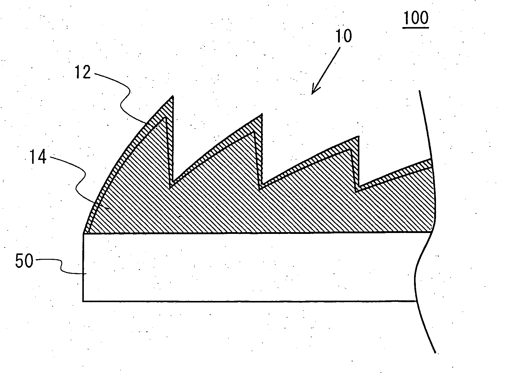
[0033]FIG. 1 shows an example of the configuration of a transmission screen 500. The transmission screen 500 has a plurality of light-transmitting members, which are substantially parallel to each other and lie near or adjacent to each other. The plurality of light-transmitting members are, for example, a Fresnel lens sheet 100 for refracting light and another optical member 400. The optical member 400 may be one of a lenticular lens sheet, a fly-eye lens sheet, a diffuser, a polarizer, a retarder, and the like, according to use of the transmission screen 500.

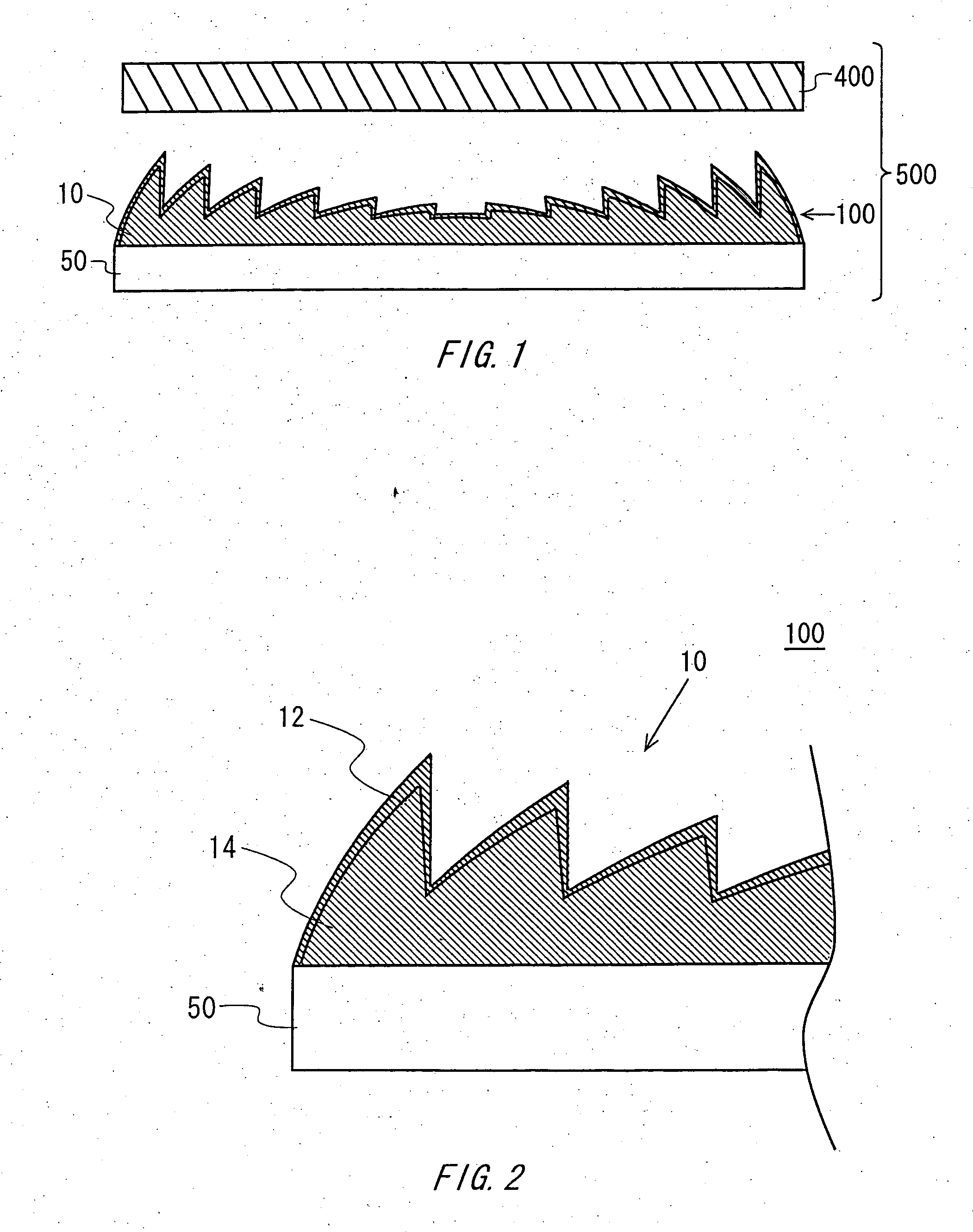
[0034] The Fresnel lens sheet 100 is an example of the lens of the present and includes a Fresnel lens layer 10 which has a pluralit...


PUM

PropertyMeasurementUnit
temperatureaaaaaaaaaa

Abstract

A lens which has a plurality of protrusions and cavities includes a core layer having a cross sectional shape smaller than and similar to a cross sectional shape of the lens; and a skin layer, which covers the core layer, having a smaller storage modulus of elasticity than that of said core layer. The lens may further include a substrate for fixing the core layer on a surface thereof, the substrate having tabular shape being made of a light-transmitting material.

Description

BACKGROUND OF THE INVENTION [0001] 1. Field of the Invention [0002] The present invention relates to a lens, a transmission screen, and a method for manufacturing the lens. More particularly, the present invention relates to a lens which has a plurality of protrusions and cavities, a transmission screen having the lens, and a method for manufacturing the lens. [0003] 2. Description of the Related Art [0004] There is a problem accompanying a lens which has a plurality of protrusions and cavities, such as, a Fresnel lens and a fly-eye lens that a tip portion of the protrusion is easy to break in case the lens contacts with another member. To enhance hardness of resin forming the lens in order to solve this problem raises another problem that the tip portion of the protrusion is easy to be damaged while a shape stability of the lens is improved. Thus, a there is an approach to be compatible with the shape stability and the scratch resistance by deciding a characteristics of resin (for ...

Claims


Application Information

Patent Timeline
Patent Type & Authority Applications(United States)
IPC IPC(8): G02B1/04G03B21/62G02B1/10G02B3/00G02B3/08
CPCG03B21/625G02B3/08
Inventor WATABE, KENICHISHIMOTSUMA, HIROYUKIIMAI, SHINICHI
Owner ARISAWA MFG CO LTD
Why Eureka
Try Eureka