Cable holder

a technology of cable holder and holder, which is applied in the direction of instruments, fuselages, optics, etc., to achieve the effect of good coverage or distribution of the adhesive used, optimized or improved distribution of the adhesive, and good adhesive coverag

Inactive Publication Date: 2005-09-08
AIRBUS OPERATIONS GMBH
View PDF19 Cites 12 Cited by
  • Summary
  • Abstract
  • Description
  • Claims
  • Application Information

AI Technical Summary

Benefits of technology

[0008] This may advantageously result in a modularly designed cable holder, for example, for electric wires. The invention makes it possible, for example, to install additional wire sections after the base element is already mounted, screwed or bonded to the corresponding structure of the aircraft, namely by simply replacing the cable holder module with another cable holder module designed for receiving additional wires.
[0012] According to another exemplary embodiment of the present invention, the pin may be provided with a ribbing or corrugation such that the distribution of an adhesive can be optimized or improved. In other words, this embodiment pertains to a cable holder that may be well suited for being bonded, for example, to cabin components with a honeycomb or laminate structure. The ribbing of the pin makes it possible to achieve a very good coverage or distribution of the adhesive used.
[0016] It may be advantageous that the cable holder module can be modularly utilized in connection with various base elements that may already be rigidly bonded to structures of the aircraft.

Problems solved by technology

This may be advantageous in the assembly of aircraft because lost parts naturally need to be found and removed because such freely movable parts could represent a safety risk.

Method used


Image

  • Cable holder
  • Cable holder
  • Cable holder

Examples


first embodiment

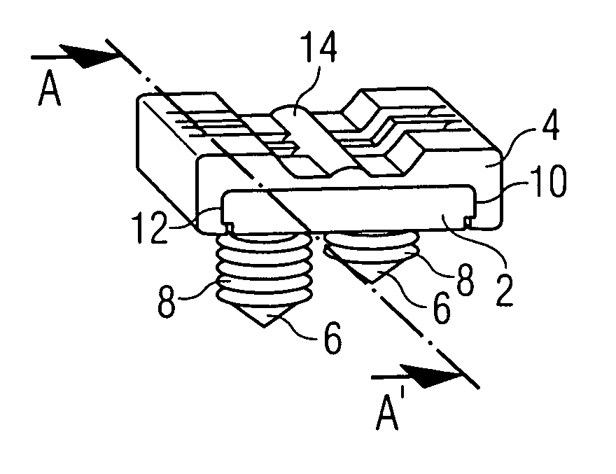
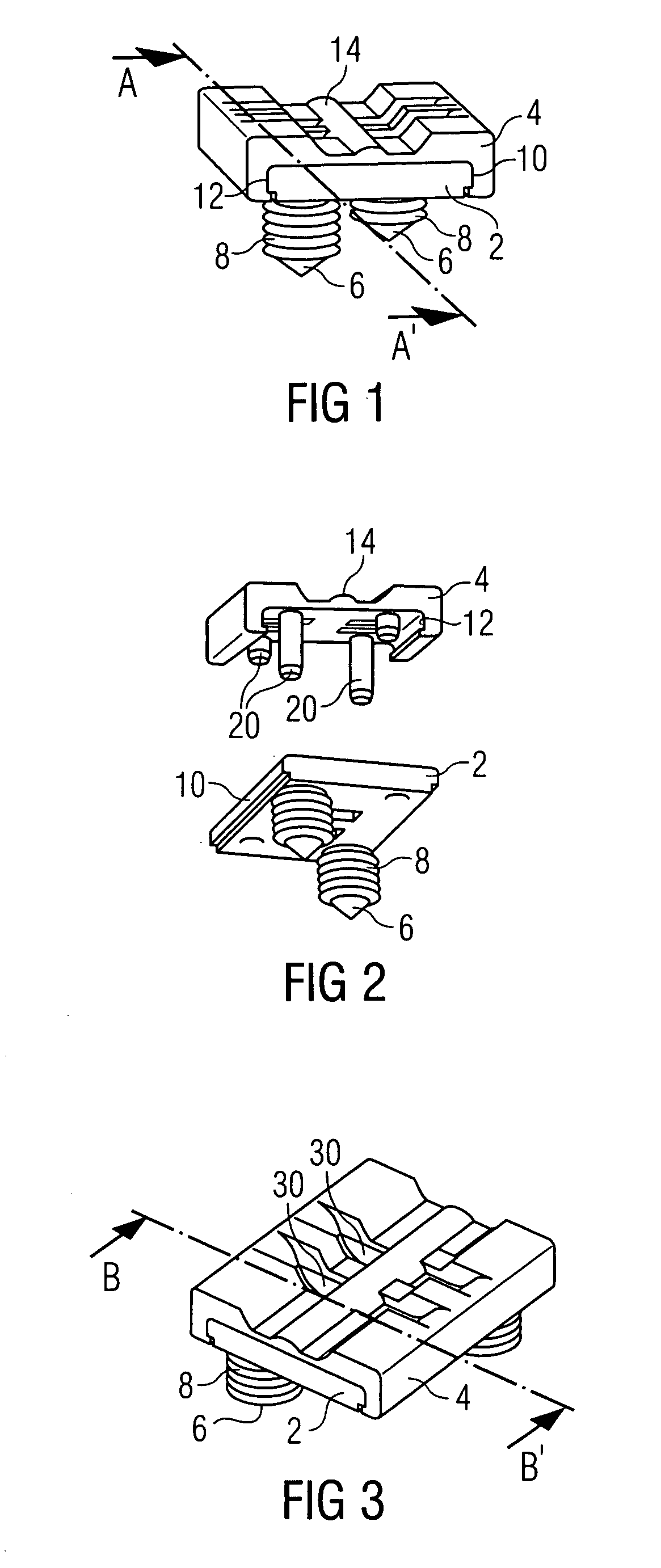
[0027]FIG. 1 shows a perspective view of a cable holder for an aircraft according to the present invention. In FIG. 1, the reference symbol 2 identifies a base element with pins 6 for being mounted on a structure of the aircraft. FIG. 1 indicates that the pins 6 are respectively provided with a ribbing 6. The ribbing of the pins 6 is realized such that a simplified distribution of the adhesive can be achieved. The pins may be coated with the adhesive such that the grooves of the ribbing 8 are filled with adhesive. Subsequently, the base element 2 is mounted on a structure of the aircraft by inserting the pins 6 into corresponding recesses in the structure, i.e., recesses with corresponding dimensions. It would be possible, for example, to realize the ribbing in a flexible fashion on its ends such that the adhesive is firmly pressed into the structure of the aircraft when the pin 6 is inserted into a slightly smaller recess.

[0028] The cable holder module is identified by the referenc...

second embodiment

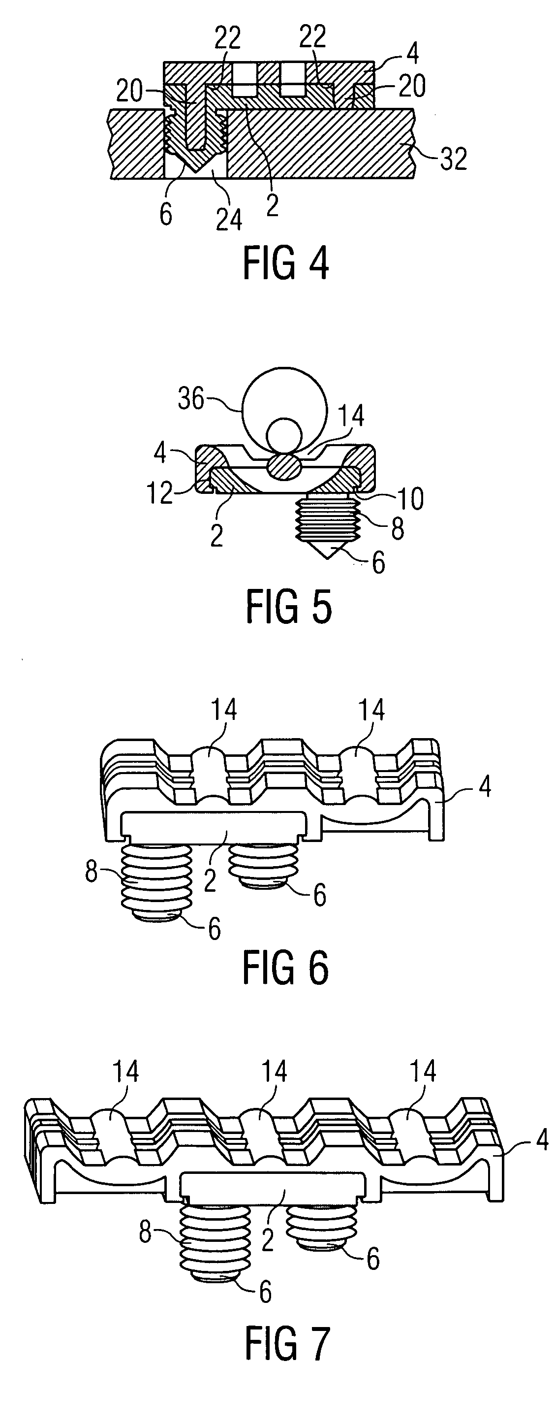
[0046]FIG. 6 shows a perspective view of a cable holder for an aircraft according to the present invention. In contrast to the embodiment shown in FIGS. 1-5, this cable holder module 4 contains two openings 14 rather than only one opening 14 for receiving the cables. The base element 2 is designed analogous to the base element 2 shown in FIG. 1.

third embodiment

[0047]FIG. 7 shows a perspective view of a cable holder according to the present invention. In the embodiment shown in FIG. 7, the base element 2 is designed analogous to that shown in FIGS. 1-6. However, the cable holder module 4 is designed for receiving a larger number of cables. The embodiment shown in FIG. 7 comprises three openings 14 for receiving wire sections or cables.

[0048]FIGS. 6 and 7, in particular, elucidate that the same base element 2 can be used in connection with various cable holder modules 4 that are respectively designed for receiving larger / smaller cables or a larger number of cables. This allows a modular utilization of the base element and the cable holder modules, as well as a flexible installation of the cables and simple modifications thereof.

[0049] It should be noted that the term “comprising” does not exclude other elements or steps and that “a” or “an” does not exclude a plurality. Also, elements described in association with different embodiments may...


PUM


Abstract

A cable holder with a cable holder module that can be separably connected to a base element. The base element contains a mount for mounting on a structure of the aircraft. The cable holder module can be exchanged, if so required, which allows simple installation of other or additional cable harnesses.

Description

CROSS-REFERENCE TO RELATED APPLICATIONS [0001] This application claims the benefit of the filing date of U.S. Provisional Patent Application No. 60 / 598,273 filed Aug. 3, 2003, the disclosure of which is hereby incorporated herein by reference.BACKGROUND OF THE INVENTION [0002] The present invention relates to an arrangement for holding and guiding wires, wire sections, cable harnesses and cables in aircraft. The present invention relates, in particular, to a cable holder for an aircraft, a base element for a cable holder for an aircraft, a cable holder module for a cable holder for an aircraft, a cable holder kit, as well as an aircraft with a corresponding cable holder. [0003] In the field of aircraft cabin engineering, the electric / electronic cabin systems, e.g., the illumination systems, communications systems, etc., are undergoing fast-paced developments, wherein more and more cabin systems are nowadays integrated into cabin components. [0004] The cabin systems need to be electr...

Claims


Application Information

Patent Timeline
Patent Type & Authority Applications(United States)
IPC IPC(8): B64C1/00B64D47/00G02B6/00H02G3/04H02G3/30H02G3/32
CPCB64C1/406B64D47/00H02G3/32H02G3/30H02G3/26
Inventor LOHR, HAUKE
Owner AIRBUS OPERATIONS GMBH
Why Eureka
Try Eureka