Network device

a network device and network technology, applied in the field of digital devices, can solve the problems of incomplete function sharing between mutual network devices and devices that cannot be reconstituted

Inactive Publication Date: 2005-09-08
HITACHI LTD
View PDF7 Cites 45 Cited by
  • Summary
  • Abstract
  • Description
  • Claims
  • Application Information

AI Technical Summary

Benefits of technology

[0015] These and other objects, features and advantages of the present invention will become more apparent in l

Problems solved by technology

As indicated in the foregoing, there are problems, in which a conventional network device cannot reconstruct dynamically the device description owned by the network device itself corresponding to a change of device arrangements of the network devices

Method used


Image

  • Network device
  • Network device
  • Network device

Examples


first embodiment

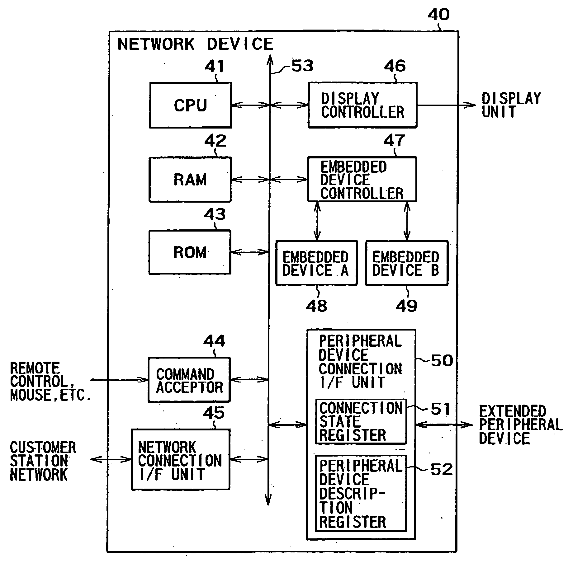
[0052]FIG. 4 is a block diagram of a network device of the present invention. In FIG. 4, a numeric reference 40 is a network device, a numeric reference 41 is a CPU, a numeric reference 42 is a RAM, a numeric reference 43 is a ROM, a numeric reference 44 is a command acceptor, a numeric reference 45 is a network connection I / F unit, a numeric reference 46 is a display controller, a numeric reference 47 is an embedded device controller, a numeric reference 48 is an embedded device A, a numeric reference 49 is an embedded device B, a numeric reference 50 is a peripheral device connection I / F unit, a numeric reference 51 is a connection state register, and a numeric reference 52 is a peripheral device description register.

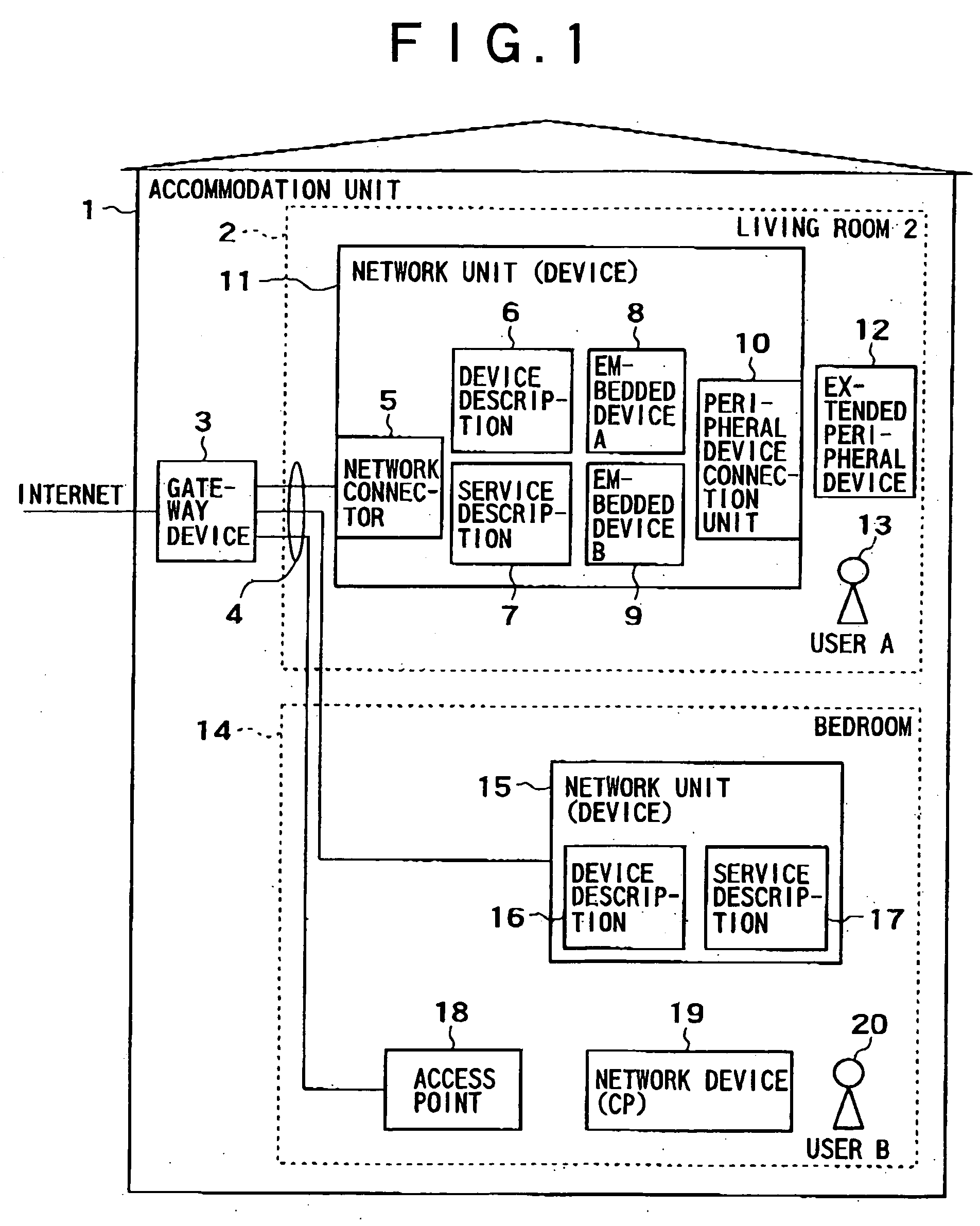
[0053] The network unit (device) 40 of FIG. 4 is a device in compliance with the UPnP standard. The network unit (device) 40 is a network device corresponding to each of the network units (devices) 11 and 15 of FIG. 1 This network unit (device) 40 includes the CPU 41,...

second embodiment

[0121]FIGS. 12A, 12B, and 12C are flowcharts of executing the procedures of the description restructuring and notification programs of the network device of the present invention. Then, these procedures are explained herein. The description restructuring and notification programs described herein are executed if the embedded device described in the device information table malfunctions or the bits for reflecting the active flag in the description are changed explicitly by the user.

[0122] First, the procedure of deleting information of the fault embedded device from the device description with reference to FIG. 12A is explained.

[0123] (1) If the fault of the embedded device is notified, the active flag of the device Information table is referred to, the line of describing “10b” in the active flag, namely, the line of indicating that the embedded device cannot be provided to the outside, is searched, and it is determined as a result of searching whether or not the corresponding line ...


PUM


Abstract

There are disclosed a digital device in compliance with UPnP and its telecommunication method for restructuring a device description in accordance with a change of arrangements of own digital devices, such as a change of connection of extended peripheral devices, for example, and transmitting and reflecting a restructured device description to other digital devices. It is determined whether or not a change for the peripheral device of the own digital device is made by referring to a device information table stored in a memory for storing information for the peripheral device included in the own digital device. If it is determined that there is a change for the peripheral devices as a result, the device description is obtained and further a device name of the peripheral device associated with the change is obtained from the device information table. Then, the device description is updated by executing a procedure for information for the device description based on the obtained device name. Information for indicating a location for storing the updated device description, such as a new advertise message describing URL, for example, is transmitted from the own digital device to a network.

Description

CLAIM OF PRIORITY [0001] The present application claims priority from Japanese patent application serial No. 2003-422738, filed on Dec. 19, 2003, the content of which is hereby incorporated by reference into this application. BACKGROUND OF THE INVENTION [0002] The present invention relates to a digital device utilized by connecting to a network. More particularly, this invention relates to an information processing system in compliance with a plug and play system, which provides a function of a device for another device so as to enable the other device to utilize it. [0003] Recently, network information home electric appliances having a plug and play function capable of sharing the function with each other by exchanging predetermined information automatically between devices connected to a network are used. Technology, so-called Universal Plug and Play (hereinafter, refer to UPnP), has been known conventionally for realizing such a plug and play function. [0004] On the other hand, i...

Claims


Application Information

Patent Timeline
IPC IPC(8): G03F3/08G06F13/12G06F15/177G06F13/00H04L12/28H04L29/08H04Q9/00
CPCH04L12/2805H04L12/281H04L67/02H04L2012/2849H04L2012/2841
Inventor KOHINATA, NOBUAKIMIZUTANI, MIKAYAMAGISHI, TOSHIHIRO
Owner HITACHI LTD
Why Eureka
Try Eureka