Vacuum cleaner

a vacuum cleaner and vacuum cleaner technology, applied in the field of vacuum cleaners, can solve the problems of vacuum cleaners having problems in replacing filters, and achieve the effect of cleaning the inside of dust collectors with ease, enabling cleaning and replacing filters with eas

Inactive Publication Date: 2005-09-15
LG ELECTRONICS INC
View PDF24 Cites 31 Cited by
  • Summary
  • Abstract
  • Description
  • Claims
  • Application Information

AI Technical Summary

Benefits of technology

[0013] An object of the present invention is to provide a vacuum cleaner enabling cleaning an inside of a dust collector with ease.
[0014] Another object of the present invention is to provide a vacuum cleaner enabling cleaning and replacing a filter with ease.
[0023] The second discharge tube may be formed as a single body with the lower cover. A discharge tube cover is detachably provided on an upper surface of the second discharge tube for preventing impurities from being entered thereto.

Problems solved by technology

However, the related art vacuum cleaner has problems in cleaning the inside of the dust collector and replacing the filter provided in the dust collector.

Method used


Image

  • Vacuum cleaner
  • Vacuum cleaner
  • Vacuum cleaner

Examples


second embodiment

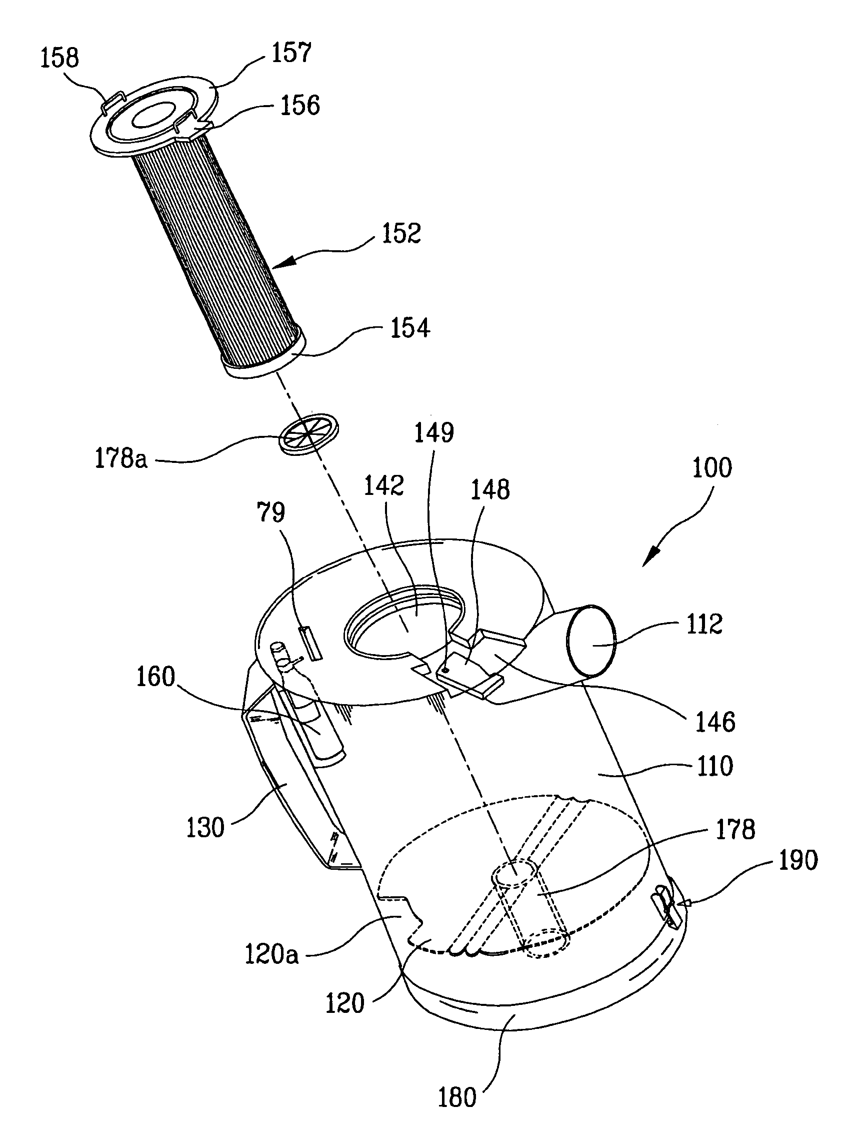
[0097] As illustrated in FIGS. 8 to 10, the dust collector assembly in accordance with the present invention includes a dust collector 110, a filter 52, and a lower cover 180.

[0098] In this case, an outside diameter of the separation plate 220 is formed to be smaller that the inside diameter of the dust collector 110. Accordingly, a gap 220a is formed between the separation plate 220 and the dust collector 110. The gap 220a plays the same role as the pass through hole 120a. In other words, impurities with large masses among the impurities drawn into the dust collector 110 are accumulated in the lower inner space of the dust collector 110.

[0099] It is desirable that the separation plate 220 and the lower cover 180 are formed as a single body. In this case, as illustrated in FIG. 10, the separation plate 220 rotates together with the lower cover 1880 and escapes to the outside of the dust collector 110 when the lower surface of the dust collector 110 is opened. At this time, for prev...

first embodiment

[0101] As illustrate in FIG. 11, a discharge tube cover 178a is provided on the upper surface of the second discharge tube 178. The discharge tube cover 178a has a same structure as that in the aforementioned

[0102] Hereinafter, the operation of the vacuum cleaner in accordance with the present invention will be described as follows.

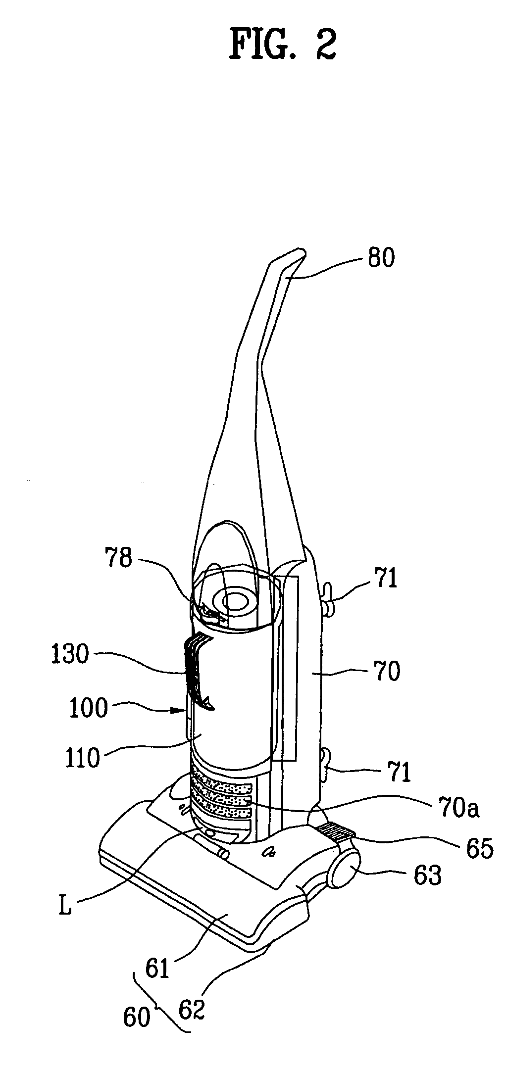
[0103] First, when the vacuum cleaner is operated, a suction force is transmitted to a suction nozzle 60 by the operation of a motor (Not shown) built in the body 70. Accordingly, air with impurities is drawn in through an inlet 62a of the suction nozzle 60.

[0104] The air is flowed into the dust collector 110 through an inflow tube 74 coupled with the inlet 62a and a suction pipe 112 formed on an outer surface of the dust collector.

[0105] In this case, impurities with large masses among the impurities contained in the air are accumulated in the lower inner space of the dust collector 120 through the pass through hole 120a or the gap 220a, and the impur...


PUM


Abstract

Disclosed is a vacuum cleaner for easily cleaning an inside of a dust collector and for easily cleaning and replacing a filter, the vacuum cleaner including a suction nozzle for drawing in air containing impurities such as dust; a main body coupled with the suction nozzle and having suction means for generating a suction force therein; a dust collector formed in a cylindrical form and detachably provided at the main body, into which the air drawn in by the suction nozzle is introduced; a suction tube provided on an outer surface of the dust collector for guiding the air drawn in by the suction nozzle to an inside of the dust collector; a separation plate for dividing an inside of the dust collector into an upper inner space and a lower inner space; a filter provided in the upper inner space of the dust collector divided by the separation plate, filtering the air drawn into the dust collector, and guiding the filtered air to the lower inner space of the dust collector; and a lower cover for discharging the air downward by selectively opening and closing a lower surface of the dust collector, the air guided by the filter.

Description

CROSS-REFERENCE TO RELATED APPLICATIONS [0001] This application claims the benefit of Korean Application No. P2004-16485, P2004-16486, P2004-16488, filed on Mar. 11, 2004, which are hereby incorporated by reference as if fully set forth herein. BACKGROUND OF THE INVENTION [0002] 1. Field of the Invention [0003] The present invention relates to a vacuum cleaner, and more particularly, to a vacuum cleaner for easily removing impurities accumulated in a dust collector. [0004] 2. Discussion of the Related Art [0005] In general, as an apparatus for removing impurities such as dust, a vacuum cleaner is used for cleaning a place that is difficult to clean with a broom or other cleaning tools. [0006]FIG. 1 illustrates a perspective view showing a related art vacuum cleaner. As illustrated in FIG. 1, the related art vacuum cleaner includes a main body 1 having suction means built therein for drawing in air, and a suction nozzle 2 for drawing in air on a floor by a suction force generated at ...

Claims


Application Information

Patent Timeline
Patent Type & Authority Applications(United States)
IPC IPC(8): A47L9/16
CPCA47L5/30A47L5/362A47L9/0444A47L9/0477A47L9/183A47L9/127A47L9/1666A47L9/1683A47L9/106
Inventor MIN, YOUNG GUNJUNG, JAE DUCK
Owner LG ELECTRONICS INC
Why Eureka
Try Eureka