Remote control security device

a remote control and security device technology, applied in the field of locks, can solve the problems of not always convenient to carry a key or remember a combination, and the user often does not know that the lock is being tampered with,

Inactive Publication Date: 2005-09-15
MASTER LOCK COMANY LLC
View PDF19 Cites 65 Cited by
  • Summary
  • Abstract
  • Description
  • Claims
  • Application Information

AI Technical Summary

Problems solved by technology

When securing objects, it is not always convenient to carry a key or remember a combination.
Furthermore, since the user of the lock is not always in the presen

Method used


Image

  • Remote control security device
  • Remote control security device
  • Remote control security device

Examples


Embodiment Construction

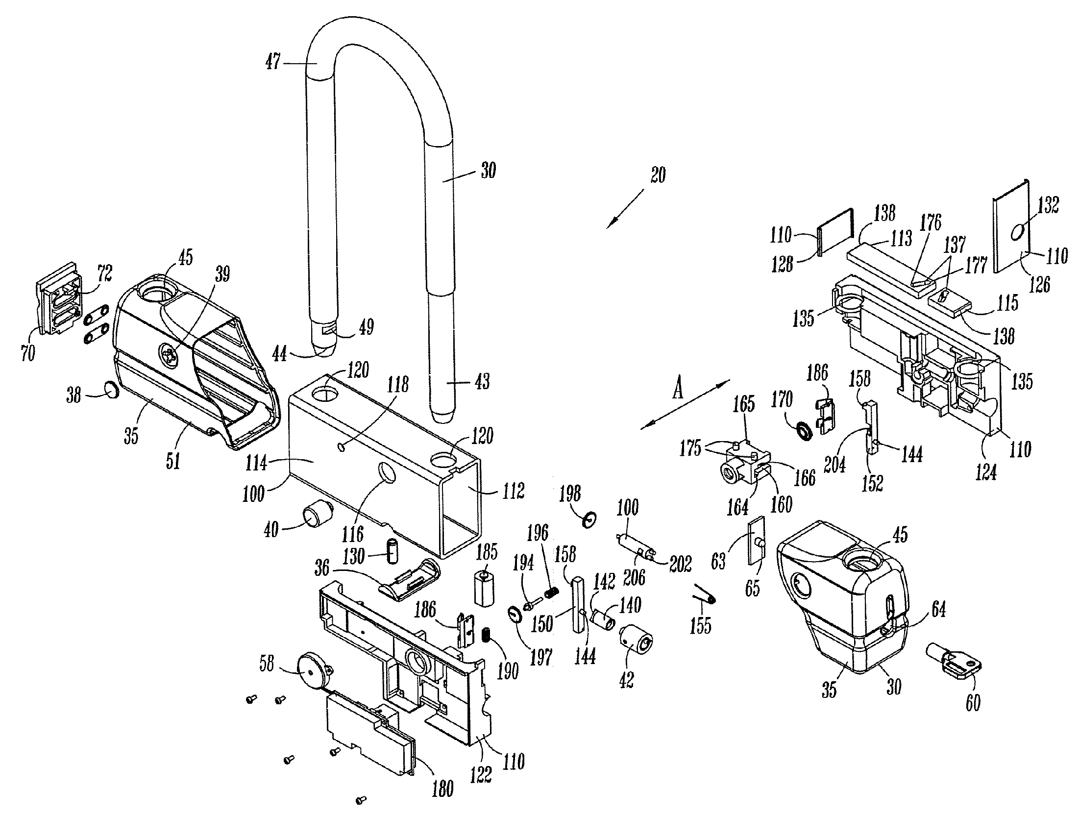
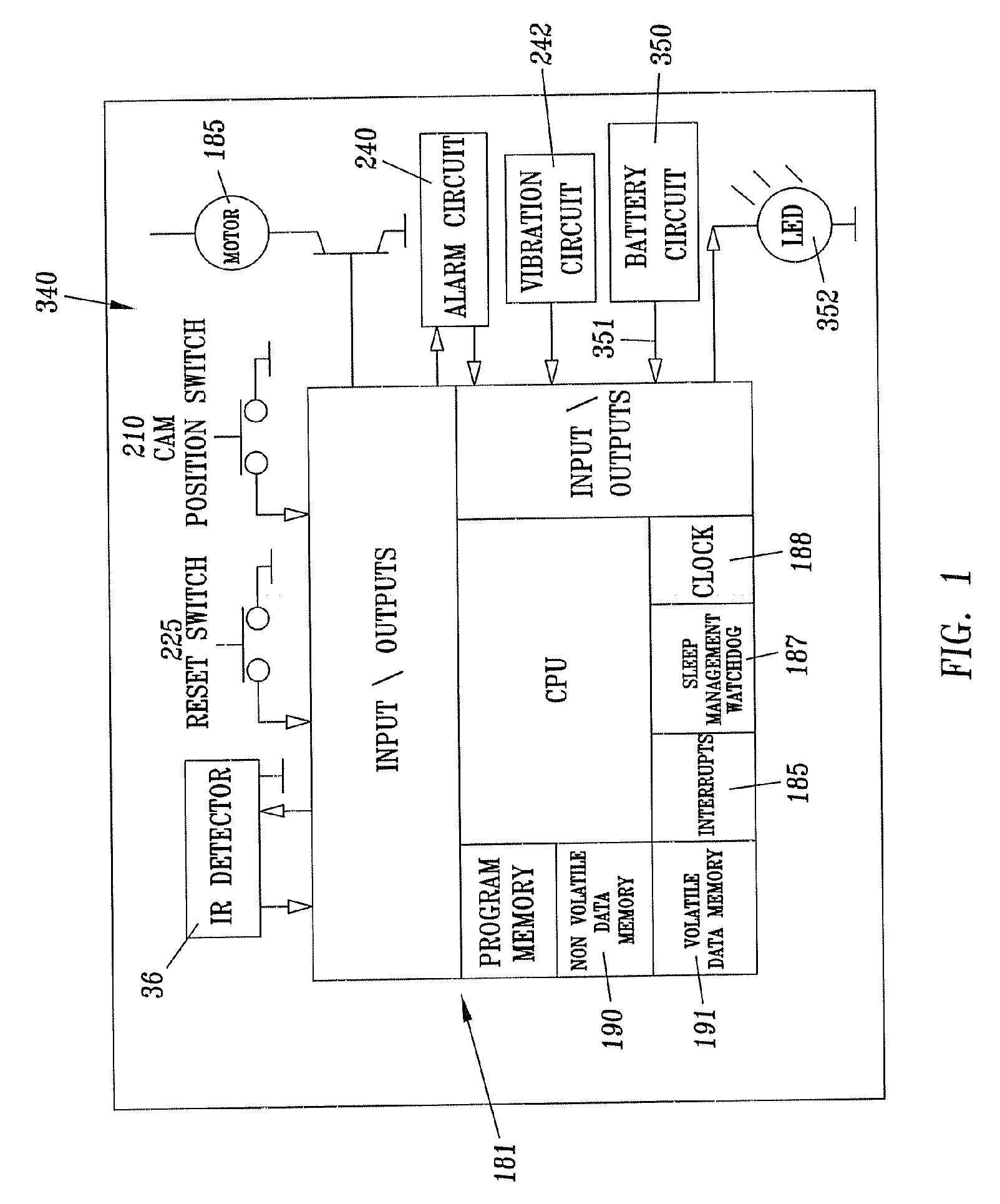
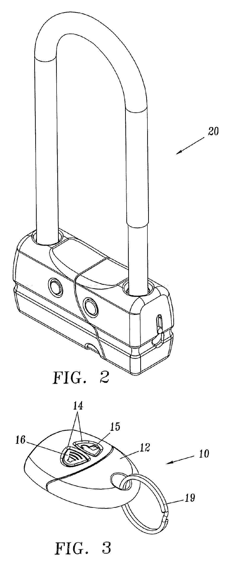
[0032]FIGS. 2 and 3 illustrate an example of a security device that can be unlocked or disarmed from a distance. This example includes a lock and a corresponding key fob that is used to active the lock. The security device can be used with a remote key fob that uses infrared, radio frequency, RFID or the like, or a remote signal from, for example, a PDA, computer, cell phone or the like, to transmit a message to the lock that will allow the user to unlock the lock from a distance away from the lock. The distance in which the security device can be unlocked from is dependent on the technology implemented. For example, most direct source devices would have a range of 1 to 15 meters, however use of other technology, such as, for example, the Internet, satellite communication or other such systems could be used to extend the distance. The security device offers convenience to the user, because they do not have to insert a key blade or dial or remember a combination. This embodiment can ...


PUM


Abstract

A lock includes two independently operating locking mechanism, one locking mechanism operating electronically and one locking mechanism operating mechanically. The lock may include a device for receiving and decoding an electronic unlock signal and a memory source for storing multiple unique unlock signals. The electronic signal may be generated from a remote source or on the lock itself. The lock also may include a button that allows unique unlock signals to be added or deleted from the lock memory.

Description

CROSS-REFERENCE TO RELATED PATENT APPLICATIONS [0001] This application claims the benefit of U.S. Provisional Patent Application No. 60 / 521,212 filed on Mar. 12, 2004, the entire disclosure of which is hereby incorporated by reference.FIELD OF THE INVENTION [0002] The present invention is directed to an improved lock, and more specifically to a lock including an electronically operated locking mechanism and a mechanically operated locking mechanism that operate independently of one another. BACKGROUND [0003] Security devices, such as locks, are used in a variety of ways to secure a variety of objects. When securing objects, it is not always convenient to carry a key or remember a combination. This is especially true for users with multiple locks, each having a different key or combination. Additionally, it can be more convenient to unlock the lock from a given distance away from the lock and without having to mechanically manipulate a portion of the lock. Furthermore, since the user...

Claims


Application Information

Patent Timeline
IPC IPC(8): B60R25/02E05B45/00E05B47/00E05B67/00
CPCE05B45/00E05B2047/0024E05B67/00E05B47/0012Y10T70/459Y10T70/5973
Inventor MARCELLE, JESSEMEEKMA, GLENNLESLIE, VINCE
Owner MASTER LOCK COMANY LLC
Why Eureka
Try Eureka