
Filter plate assembly for filter

a filter plate and filter plate technology, applied in the direction of filter separation, moving filter element filters, separation processes, etc., can solve the problems of excessive downtime, complex fully automated filter cleaning systems employed with conventional filter presses, and inability to pass liquid through the filter elemen

Active Publication Date: 2005-09-15
DUBY SEAN R
View PDF19 Cites 77 Cited by
  • Summary
  • Abstract
  • Description
  • Claims
  • Application Information

AI Technical Summary

Benefits of technology

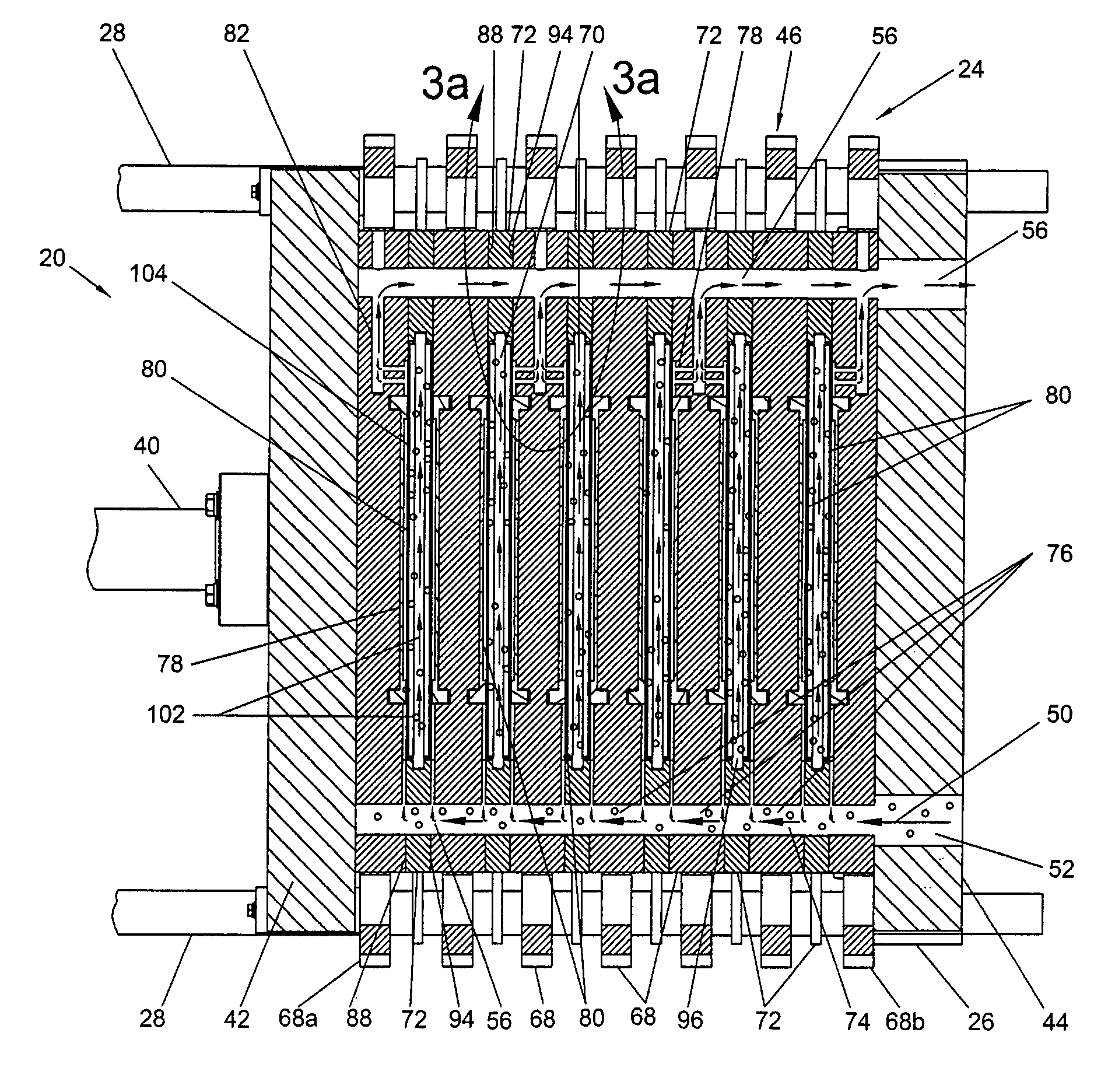
[0013] In another embodiment, a method of filtering includes forming a sealed filter chamber with a filter plate assembly. The filter plate assembly has a first filter plate, a second filter plate, and a closure. The first filter plate and the second filter plate are movable from an open position to a closed position relative to one another to partially close the filter chamber, thereby defining an open section of the filter chamber. The closure is configured to close the open section of the sealed filter chamber. A slurry is introduced into the filter chamber. A liquid of the slurry is forced through a filter media lining at least a portion of the filter chamber until a particulate cake is formed within the filter chamber, which occupies a substantial portion of the filter chamber. The closure is removed while maintaining the first filter plate and the second filter plate in the closed position and the particulate cake is discharged through the open section of the filter chamber.

Problems solved by technology

However, with this type of filtering process, once the surface of the filter element is substantially covered with solid particulate matter, liquid is no longer able to pass through the filter element.
Because as many as a hundred or more individual plates may be used, the cleaning process is very time-consuming and results in excessive down-time in which the filter press is not utilized.
Furthermore, due to the provision of multiple plates which need to be separated, fully automated filter cleaning systems employed with conventional filter presses are complex and often prohibitively expensive.

Method used


Image

  • Filter plate assembly for filter
  • Filter plate assembly for filter
  • Filter plate assembly for filter

Examples


Embodiment Construction

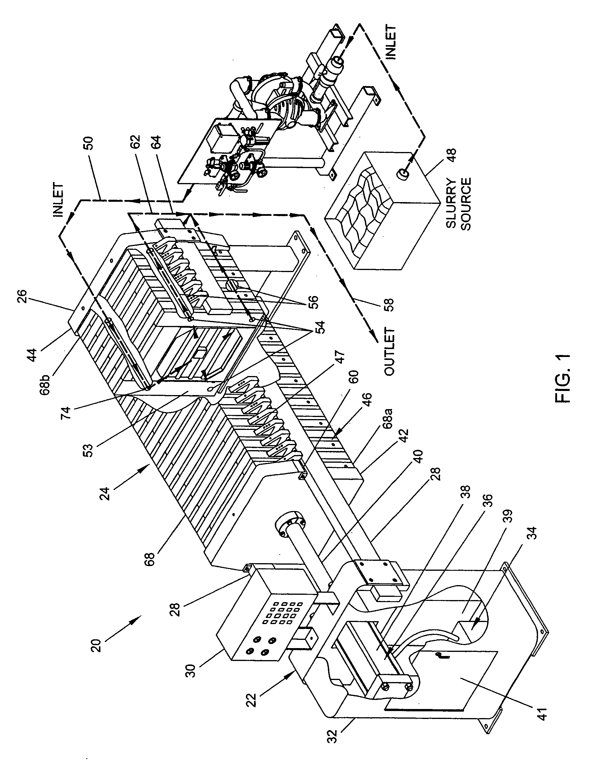
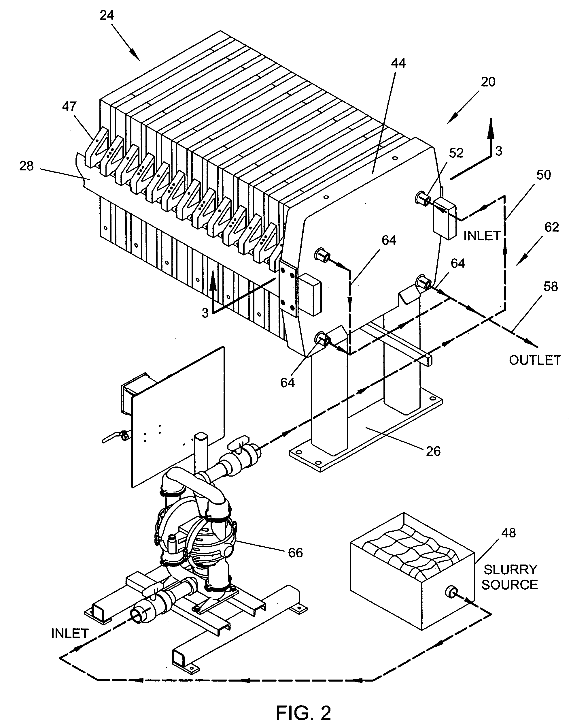
[0037] A filter press is used to separate liquid and solid components from a liquid-solid mixture, such as a slurry or sludge. For example, the filter press described herein is generally referred to by the reference numeral 20 and can be used to filter a process fluid, industrial waste, municipal waste, or perform component separation in other settings. The filter press 20 may also be used in a variety of other industries.

[0038] During the filtering process, solids accumulate and form a particulate cake within filter chambers defined by the filter press 20. The filter press 20 preferably includes a mechanism for rapidly discharging the cake from the filter chamber, without requiring the filter plates to be entirely separated from one another, as is described in greater detail below. For example, in one arrangement the cake can be removed from the filter press by using a movable closure to permit access to the filter chamber. The methods and structures disclosed herein are described...


PUM

PropertyMeasurementUnit
Lengthaaaaaaaaaa
Pressureaaaaaaaaaa
Widthaaaaaaaaaa

Abstract

A filter configured to separate the solid components and the liquid components from a slurry. The filter includes a plurality of filter plate assemblies that cooperate to define a plurality of filter chambers, each defining a perimeter having an open section when the filter plates are in a closed position relative to one another. Each filter plate assembly includes a closure configured to close the open section. Preferably, the closures are movable to an open position to permit a particulate cake to be removed from the filter chambers without separating the filter plates.

Description

RELATED APPLICATION [0001] This application claims priority from U.S. Provisional Patent Application No. 60 / 551,442, filed Mar. 9, 2004.INCORPORATION BY REFERENCE [0002] The entirety of U.S. Provisional Patent Application No. 60 / 551,442, filed Mar. 9, 2004, is hereby incorporated by reference herein and made a part of this specification. BACKGROUND [0003] 1. Field of the Invention [0004] The present invention is related generally to the field of separating solid and liquid components from a mixture. More specifically, the present invention is related to an improved filter plate assembly and related methods and filtering devices. [0005] 2. Description of the Related Art [0006] Separating the liquid and solid components of a liquid-solid mixture, or slurry, is a necessary or desirable process in many industries. In many filtering applications, the slurry is a waste product and it is desirable to separate the solid and liquid matter and dispose of them separately. Often, the solid comp...

Claims


Application Information

Patent Timeline
IPC IPC(8): B01D25/12
CPCB01D25/164B01D25/284B01D2201/34B01D2201/4046B01D25/12B01D25/386B01D25/215B01D25/285B01D25/346B01D25/38B01D25/325
Inventor DUBY, SEAN R.
Owner DUBY SEAN R
Learn More