
Single valve ready to use hose end sprayer

Active Publication Date: 2005-09-15
SILGAN DISPENSING SYST CORP
View PDF82 Cites 4 Cited by
  • Summary
  • Abstract
  • Description
  • Claims
  • Application Information

AI Technical Summary

Benefits of technology

[0006] Therefore in a preferred embodiment, one object is to provide a safe and reliable aspiration type chemical sprayer that utilizes a minimum number of components and that is relatively easy to manufacture and assemble.

Problems solved by technology

While in this concentrated form, the chemical is extremely hazardous to the consumer end user and the environment in general.

Method used


Image

  • Single valve ready to use hose end sprayer
  • Single valve ready to use hose end sprayer
  • Single valve ready to use hose end sprayer

Examples


Embodiment Construction

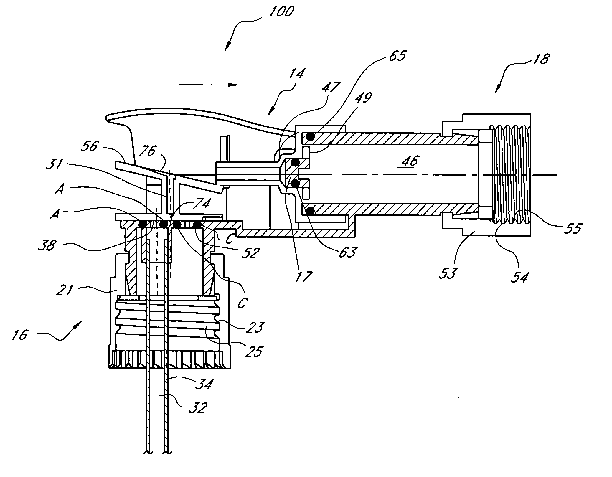
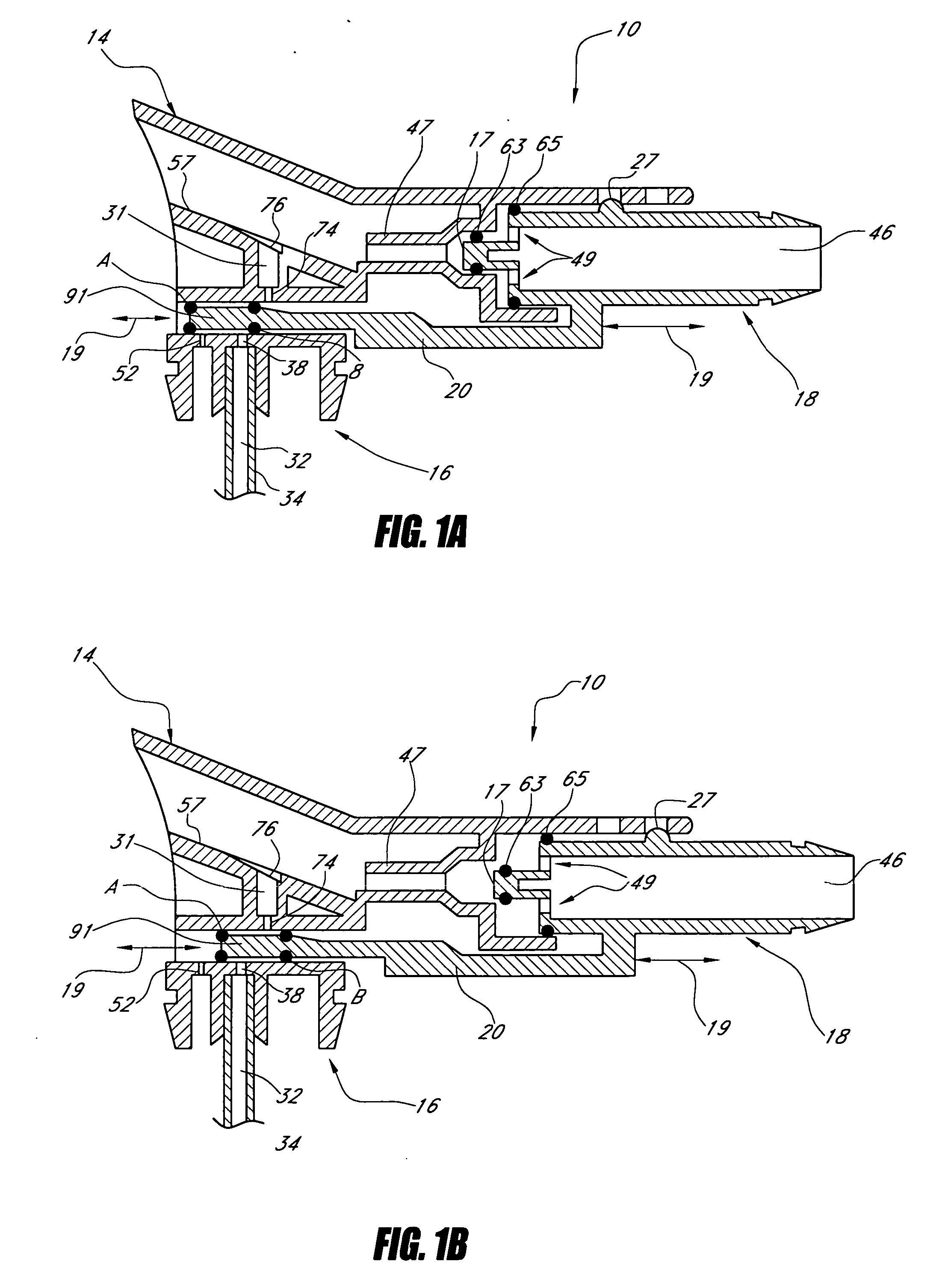
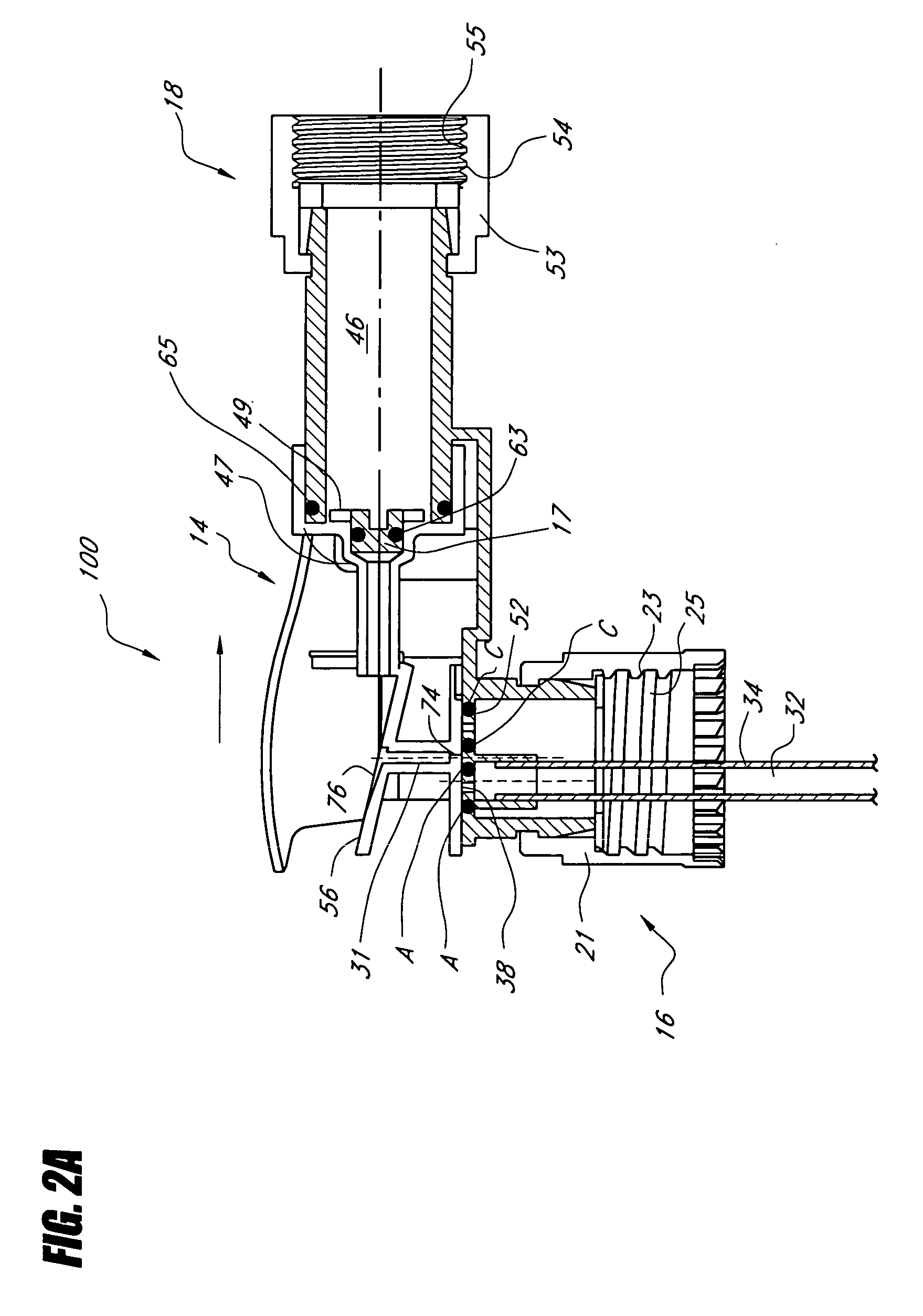
[0020] A sprayer head assembly 10 according to an exemplary embodiment is illustrated in FIGS. 1A and 1B. The sprayer head assembly 10 is connected to a chemical container (not shown). The sprayer head assembly 10 includes a sprayer head 14, a container connection portion 16 and a supply fluid connection portion 18. The sprayer head assembly 10 may be made of any suitable material that is resistant to and compatible with the chemical fluid to be sprayed. However, a flexible plastic material, such as polypropylene, is preferred because it is resilient yet durable.

[0021] With reference to FIG. 1, the supply fluid connection portion 18 is coupled to a slide or sliding member 20, which in the illustrated embodiment lies between the sprayer head 14 and the container connection portion 16. As will be explained below, the sliding member 20 and the sprayer connection portion 18 are moveable in a longitudinal direction (see arrows 19 in FIGS. 1A and 1B) with respect to the container connect...


PUM


Abstract

Disclosed are embodiments related to a chemical sprayer that comprises a sprayer head assembly and a container. The container defines a cavity for storing a chemical to be sprayed. A valve may be longitudinally moveable from an open position to a closed position. In the closed position, the valve may block a chemical passage, a vent passage, and a carrier fluid passage. In an open position, these passages are opened.

Description

RELATED APPLICATIONS [0001] This application claims priority pursuant to 35 U.S.C. 119(e) to co-pending U.S. Provisional Patent Application Ser. Nos. 60 / 544,728, filed Feb. 13, 2004, and 60 / 546,553, filed Feb. 20, 2004, which are hereby incorporated by reference in their entirety.BACKGROUND OF THE INVENTION [0002] 1. Field of the Invention [0003] The present invention relates to chemical dispensing sprayers and, in particular, to aspiration-type sprayers that use a relatively large amount of carrier fluid for dispensing a relatively small amount of a chemical solution. [0004] 2. Description of the Related Art [0005] Every year consumers apply thousands of gallons of chemicals such as fertilizers or pesticides to plants, lawns, flowers, vegetable gardens and other organic type vegetation. Typically, such chemicals are sold in plastic containers in a concentrated form. While in this concentrated form, the chemical is extremely hazardous to the consumer end user and the environment in ...

Claims


Application Information

Patent Timeline
IPC IPC(8): A62C5/02
CPCB05B1/267B05B7/2448B05B7/1209B05B1/3066
Inventor SHANKLIN, DONALD J.ENGLHARD, RONALD F.
Owner SILGAN DISPENSING SYST CORP
Features
  • Generate Ideas
  • Intellectual Property
  • Life Sciences
  • Materials
  • Tech Scout
  • Unparalleled Data Quality
  • Higher Quality Content
  • 60% Fewer Hallucinations
Learn More