Elastic shaft coupling

Active Publication Date: 2005-09-15
CENTA ANTRIEBE KIRSCHEY GMBH
View PDF14 Cites 4 Cited by
  • Summary
  • Abstract
  • Description
  • Claims
  • Application Information

AI Technical Summary

Benefits of technology

[0008] It is, therefore, the principal object of the present invention to provide an elastic coupling which is of as sim

Problems solved by technology

To open the ring, the system must be disassembled and such openings and disassembly is not possible without enabling the assembly to shift or move in the axial directio

Method used


Image

  • Elastic shaft coupling
  • Elastic shaft coupling
  • Elastic shaft coupling

Examples


Example

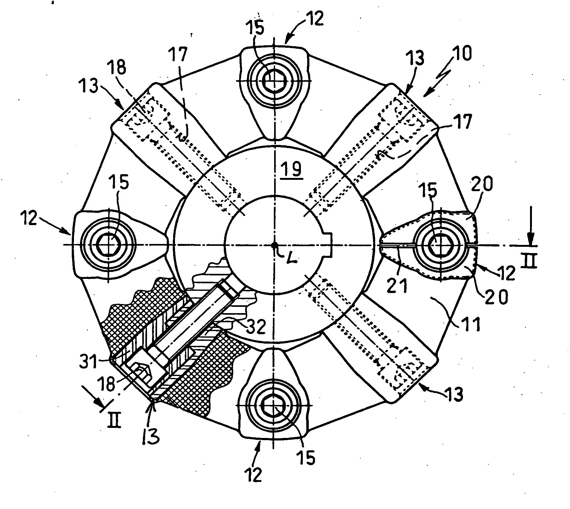
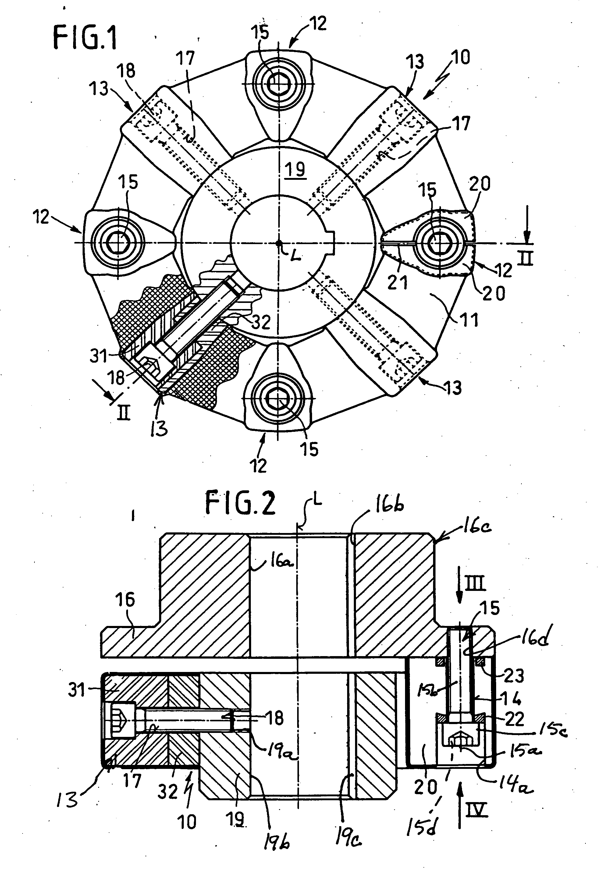
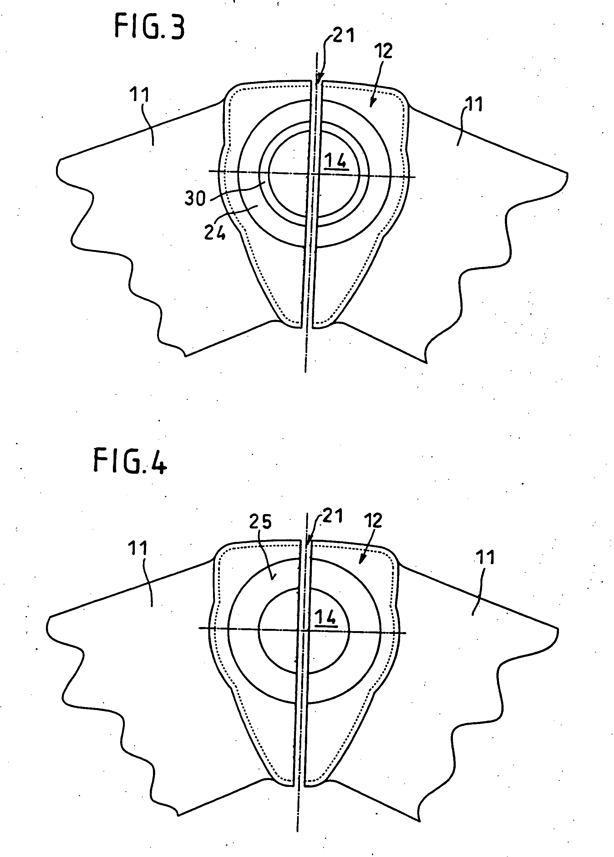
[0041] In the drawing I have shown an elastic shaft coupling which as a whole is represented at 10. The shaft coupling 10 comprises substantially a polygonal ring element 11, preferably of an elastomer and especially of rubber, into which at uniform angular spacing, metal bodies 12 and 13 are anchored by vulcanizing them to the rubber. The different metal bodies 12 and 13 alternate angularly about the coupling 10 from one to another. The metal bodies 12 have throughgoing bores 14, the centers of which all lie along the same circle centered on the longitudinal or rotation axis L of the shaft coupling. The throughgoing bores 14 are traversed by fastening screws 15 whose longitudinal axes 15a (FIG. 2) run parallel to the rotation axis L which also may be referred to here as the longitudinal axis of the coupling system. The fastening screws 15 serve to affix the elastic body to one of two coupling halves or members. i.e. the driving member or the driven member which is provided as a fla...


PUM


Abstract

An elastic shaft coupling has one of the metal parts embedded in the elastic coupling ring and vulcanized thereto, split into two segments which are held together by a fixing element wholly within those metal segments in the form of a clamping ring or centering ring or both traversed by a screw threaded into the driving or driven member of the coupling.

Description

FIELD OF THE INVENTION [0001] My present invention relates to an elastic shaft coupling and, more particularly, to a shaft coupling of the type in which an elastomeric body is provided between the driving and driven coupling halves or between the driving and driven members of the shaft coupling which are connected respectively to the driving and driven shafts. BACKGROUND OF THE INVENTION [0002] One type of elastic shaft coupling has, between a driving and a driven coupling half or coupling member, a substantially ring-shaped or annular coupling element composed of elastic material, usually an elastomer and especially rubber, whereby, for connection of that coupling element or body with the coupling halves or the driving and driven members of the coupling which are connected to the respective shafts, metallic members are embedded in, connected by vulcanization to, or otherwise form parts of the elastic body. [0003] These metal members are provided with bores traversed by fastening sc...

Claims


Application Information

Patent Timeline
IPC IPC(8): F16D3/52F16D3/78
CPCY10T403/10F16D3/78F16D3/68
Inventor KIRSCHEY, GERHARD
Owner CENTA ANTRIEBE KIRSCHEY GMBH
Why Eureka
Try Eureka