Local reinforcing method for concrete silo

A local reinforcement and concrete technology, which is applied in building maintenance, building types, buildings, etc., can solve the problems of large force, and achieve the effect of reasonable structure, reduced bearing capacity and uniform force

Pending Publication Date: 2022-02-11
HUATIAN NANJING ENG & TECH CORP MCC +1
View PDF5 Cites 0 Cited by
  • Summary
  • Abstract
  • Description
  • Claims
  • Application Information

AI Technical Summary

Problems solved by technology

[0003] The purpose of the present invention is to overcome the defects of the current concrete silo structure that the local force is too large, provide a local reinforcement method for the concrete silo, effectively improve the horizontal bearing capacity of the concrete silo, and prevent the cracking of the concrete silo

Method used


Image

  • Local reinforcing method for concrete silo
  • Local reinforcing method for concrete silo
  • Local reinforcing method for concrete silo

Examples


Embodiment 1

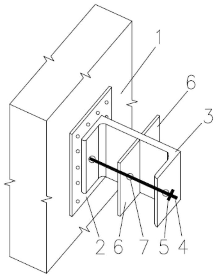
[0031] Such as figure 2 Among them, a row of bolt holes 7 is set on the U-shaped support frame 3 and the reinforcement plate 6, and the high-strength bolts 4 pass through the bolt holes 7 on the U-shaped support frame 3 and the reinforcement plate 6 from the outside to the inside, and the bolts are located on the U-shaped support frame. 3. A jacking nut 5 is arranged on the outer part; the high-strength bolt 4 makes its front end press against the steel backing plate 2, and at the same time, the jacking nut 5 is turned outward, so that the jacking nut 5 is tightened outward against the U-shaped support frame 3, And a certain prestress is applied to the steel backing plate 2 .

Embodiment 2

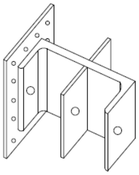
[0033] Such as image 3 Among them, two rows of bolt holes 7 are set on the U-shaped support frame 3 and the reinforcing plate 6, and the two rows of screw holes 7 are arranged at equal vertical intervals. The high-strength bolts 4 pass through the bolt holes 7 on the U-shaped support frame 3 and the reinforcement plate 6 from the outside to the inside, and set the tightening nuts 5 on the parts outside the U-shaped support frame 3; the high-strength bolts 4 make the front end tighten The steel backing plate 2 is rotated outwardly at the same time the clamping nut 5, so that the clamping nut 5 is pressed against the U-shaped support frame 3 outwardly, and a certain prestress is applied to the steel backing plate 2.

Embodiment 3

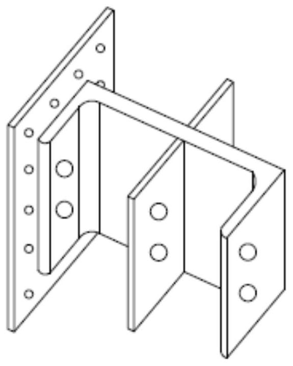
[0035] Such as Figure 4 Among them, three rows of bolt holes 7 are arranged on the U-shaped support frame 3 and the reinforcing plate 6, and the three rows of screw holes 7 are arranged at equal vertical intervals. The high-strength bolts 4 pass through the bolt holes 7 on the U-shaped support frame 3 and the reinforcement plate 6 from the outside to the inside, and set the tightening nuts 5 on the parts outside the U-shaped support frame 3; the high-strength bolts 4 make the front end tighten The steel backing plate 2 is rotated outwardly at the same time the clamping nut 5, so that the clamping nut 5 is pressed against the U-shaped support frame 3 outwardly, and a certain prestress is applied to the steel backing plate 2.


PUM


Abstract

The invention provides a local reinforcement method for a concrete silo. A steel base plate is anchored on a surface of an outer wall of the silo; a U-shaped supporting frame is welded to the outer surface of the steel base plate; bolt holes are formed in the support frame; bolts penetrate through bolt holes of the supporting frames from outside to inside to abut against the outer surface of the steel base plate; the bolts are rotated to apply certain prestress to the steel base plate. According to the method, the bolts are used for externally supporting the steel plate to apply prestress, the defect that the requirement for anchoring is high is overcome, the bearing capacity to the supporting structure and the foundation is reduced, and the method has the advantages of being reasonable in structure, uniform in stress, good in cooperative work performance and the like.

Description

technical field [0001] The invention relates to a local reinforcement method for a concrete silo, which belongs to the field of civil engineering and building reinforcement. Background technique [0002] At present, with the continuous increase of the diameter, height and capacity of the concrete silo, the force of the silo and the crack control of the silo wall have become very prominent problems. But only by improving the concrete strength grade and increasing the steel bar of the warehouse wall to meet the crack control requirements, the actual effect is not very ideal and the cost is very high. At the same time, due to the large diameter and dense spacing of the steel bars, the overlapping length of the steel bars is also long, which makes the construction very inconvenient. Contents of the invention [0003] The purpose of the present invention is to overcome the defect of excessive local stress in the current concrete silo structure, provide a local reinforcement me...

Claims


Application Information

Patent Timeline
IPC IPC(8): E04H7/26E04G23/02
CPCE04H7/26E04G23/0218E04G23/0225
Inventor 张莹陈超陈祥勇
Owner HUATIAN NANJING ENG & TECH CORP MCC
Why Eureka
Try Eureka