Synthetic model casting

a synthetic model and casting technology, applied in the field of manufacturing processes, can solve the problems of increasing the complexity and complexity of the cooling circuit inside the turbine blade, reducing the overall efficiency of the engine, and adding to the complexity of the already complex ceramic core used in typical investment casting of the turbine blad

Active Publication Date: 2005-09-22
GENERAL ELECTRIC CO
View PDF27 Cites 56 Cited by
  • Summary
  • Abstract
  • Description
  • Claims
  • Application Information

AI Technical Summary

Problems solved by technology

The cooling circuits inside turbine blades are becoming more and more complex and intricate for tailoring the use of the limited pressurized cooling air and maximizing the cooling effectiveness thereof.
Any such cooling air bled from the compressor during operation for cooling the turbine blades is not used in the combustion process and correspondingly decreases the overall efficiency of the engine.
The introduction of the double wall construction and the narrow secondary flow channels adds to the complexity of the already complex ceramic cores used in typical investment casting of turbine blades.
Since the ceramic core identically matches the various internal voids in the airfoil which represent the various cooling channels and features thereof, it becomes correspondingly more complex as the cooling circuit increases in complexity.
As the ceramic core legs become thinner, such as for the secondary channels, their strength correspondingly decreases which leads to a reduction in useful yield during the manufacture of the cores that are subject to brittle failure during handling.

Method used


Image

  • Synthetic model casting
  • Synthetic model casting
  • Synthetic model casting

Examples


Embodiment Construction

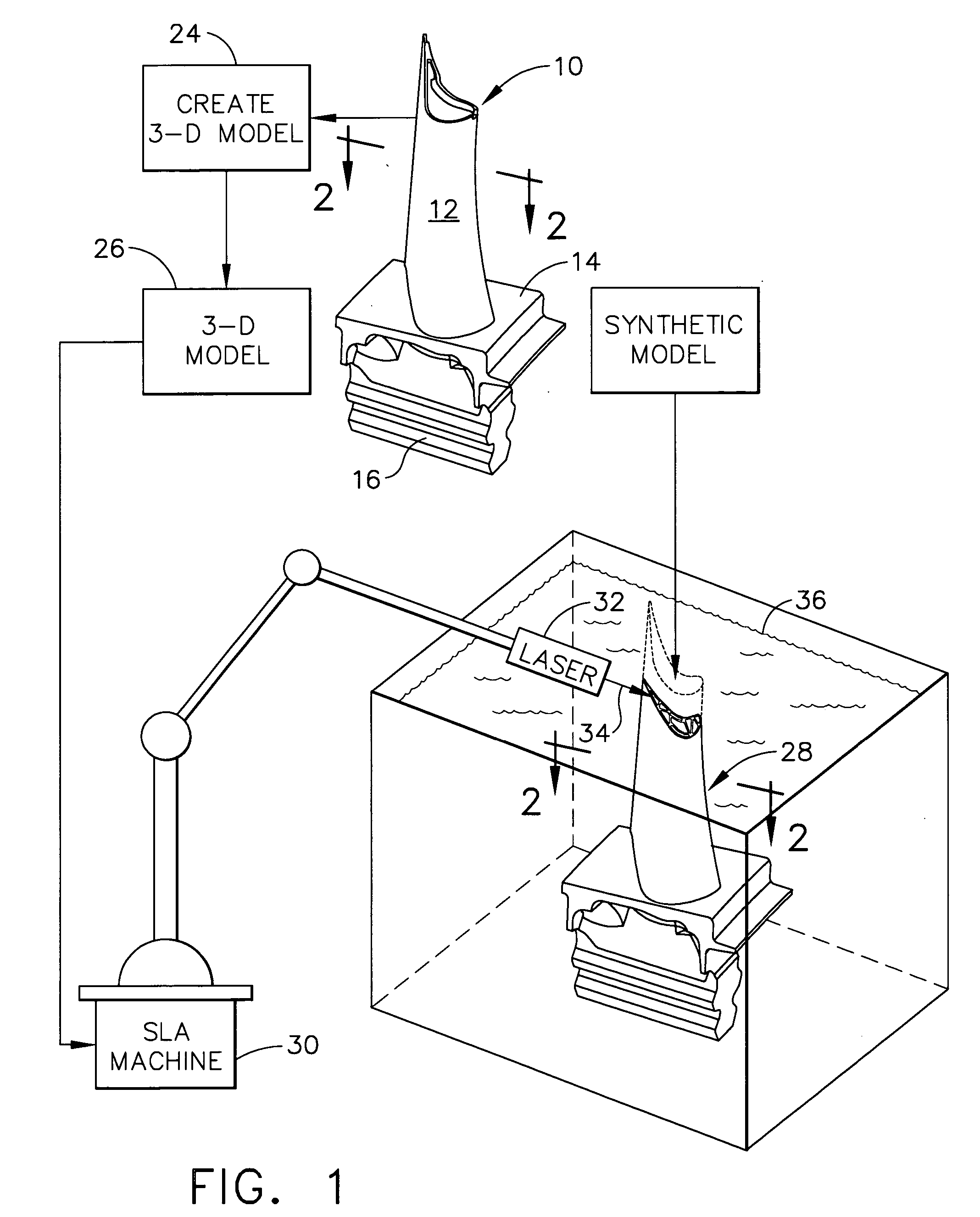
[0036] Illustrated in FIG. 1 is a component 10 for being replicated by casting. The component may have any suitable configuration for casting, and is in the exemplary embodiment of a turbine rotor blade for a gas turbine engine.

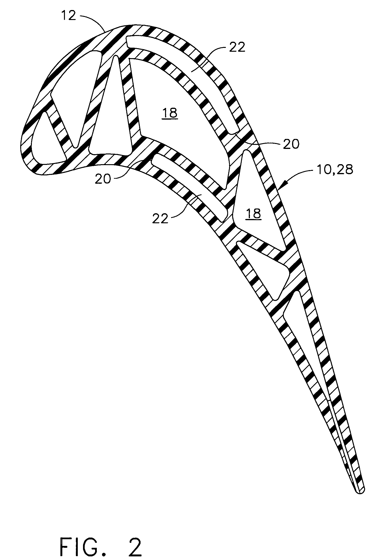
[0037] The exemplary turbine blade 10 includes an airfoil 12 having a generally concave pressure side and an opposite generally convex suction side extending in chord between opposite leading and trailing edges, and extending in radial span between a root and an outer tip.

[0038] The airfoil is integrally joined to a platform 14 at the root thereof which defines the inner boundary for the hot combustion gases which pass over the airfoil during operation in the engine. A multilobe mounting dovetail 16 is integrally formed below the platform for mounting the blade in a corresponding dovetail slot in the perimeter of a turbine rotor disk (not shown).

[0039] The turbine blade illustrated in FIG. 1 has a complex 3-D configuration and external profile as required ...


PUM

PropertyMeasurementUnit
thickaaaaaaaaaa
temperatureaaaaaaaaaa
thicknessaaaaaaaaaa

Abstract

A synthetic model of a component is created from a 3-D numerical model thereof. A core is then cast inside the synthetic model. The synthetic model may then be removed from the cast core, and then the cast core is used for casting an authentic component therearound. The core is removed from inside the authentic component, which authentic component precisely matches the original synthetic model therefor.

Description

[0001] This application is a Continuation of copending prior application Ser. No. 10 / 885,142; filed Jul. 06, 2004; and a Continuation-in-Part of copending prior application Ser. No. 10 / 617,552; filed Jul. 10, 2003, both prior applications being hereby incorporated herein by reference.BACKGROUND OF THE INVENTION [0002] The present invention relates generally to manufacturing processes, and, more specifically, to casting. [0003] Investment casting or the lost-wax process is used for forming complex three dimensional (3-D) components of a suitable material such as metal. An exemplary cast component is the typical turbine rotor blade of gas turbine engine. [0004] A turbine blade includes an airfoil integrally joined at its root with a blade platform below which is integrally joined a multilobed supporting dovetail. The airfoil is hollow and includes one or more radial channels extending along the span thereof that commence inside the blade dovetail which has one or more inlets for recei...

Claims


Application Information

Patent Timeline
Patent Type & Authority Applications(United States)
IPC IPC(8): B22C9/04B22C9/10B29C67/00
CPCB29C67/0051B22C9/10B33Y80/00Y02P10/25
Inventor WANG, HSIN-PANGLEE, CHING-PANG
Owner GENERAL ELECTRIC CO
Why Eureka
Try Eureka