
Frame construction for a vehicle

a frame and vehicle technology, applied in the field of vehicle frame construction, can solve the problems of limited kit effectiveness, impose certain design restrictions on the vehicle, and few vehicles designed to capitaliz

Inactive Publication Date: 2005-09-22
BOMBARDIER RECREATIONAL PROD INC
View PDF52 Cites 46 Cited by
  • Summary
  • Abstract
  • Description
  • Claims
  • Application Information

AI Technical Summary

Benefits of technology

The present invention provides a frame assembly for a vehicle that includes a tunnel, an engine cradle, and a sub-frame. The assembly also includes a forward support assembly, an upper column, and a rear brace assembly that connect at an apex above the upper column. The frame assembly forms a pyramidal construction, and can support a steering shaft and a rear wheel or two front wheels. The technical effects of the invention include improved stability, better weight distribution, and better steering performance.

Problems solved by technology

Despite this, snowmobiles, ATVs, and other recreational vehicles often do not share a common design approach or a commonality of components.
The narrow width, however, imposes certain design restrictions on the vehicle.
Despite this, there have been few vehicles designed that capitalize on these similarities.
However, such kits are limited in their effectiveness because the two vehicles are so completely different from one another in their basic designs.
The resulting, converted vehicles suffer from drawbacks that are associated with the purpose for which the primary vehicle was designed.
For example, a snowmobile converted to an ATV is not expected to be able to traverse the same type of terrain as a pure ATV.
Similarly, an ATV that has been converted to a snowmobile is not expected to be able to traverse the same terrain that a pure snowmobile can.

Method used


Image

  • Frame construction for a vehicle
  • Frame construction for a vehicle
  • Frame construction for a vehicle

Examples


Embodiment Construction

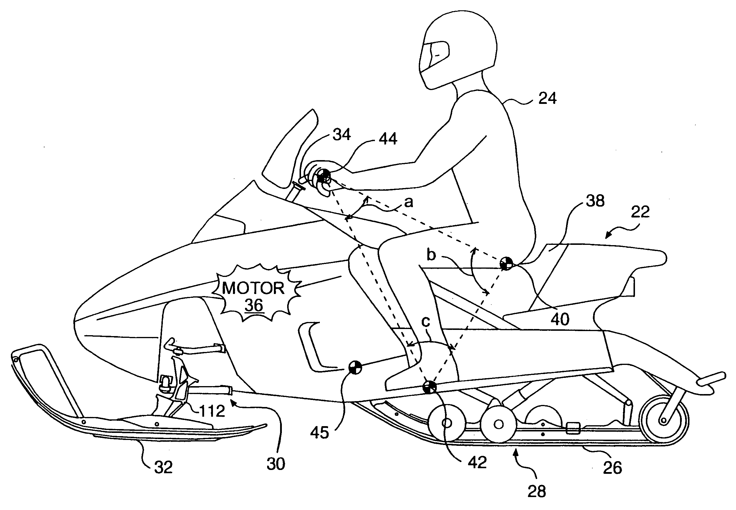
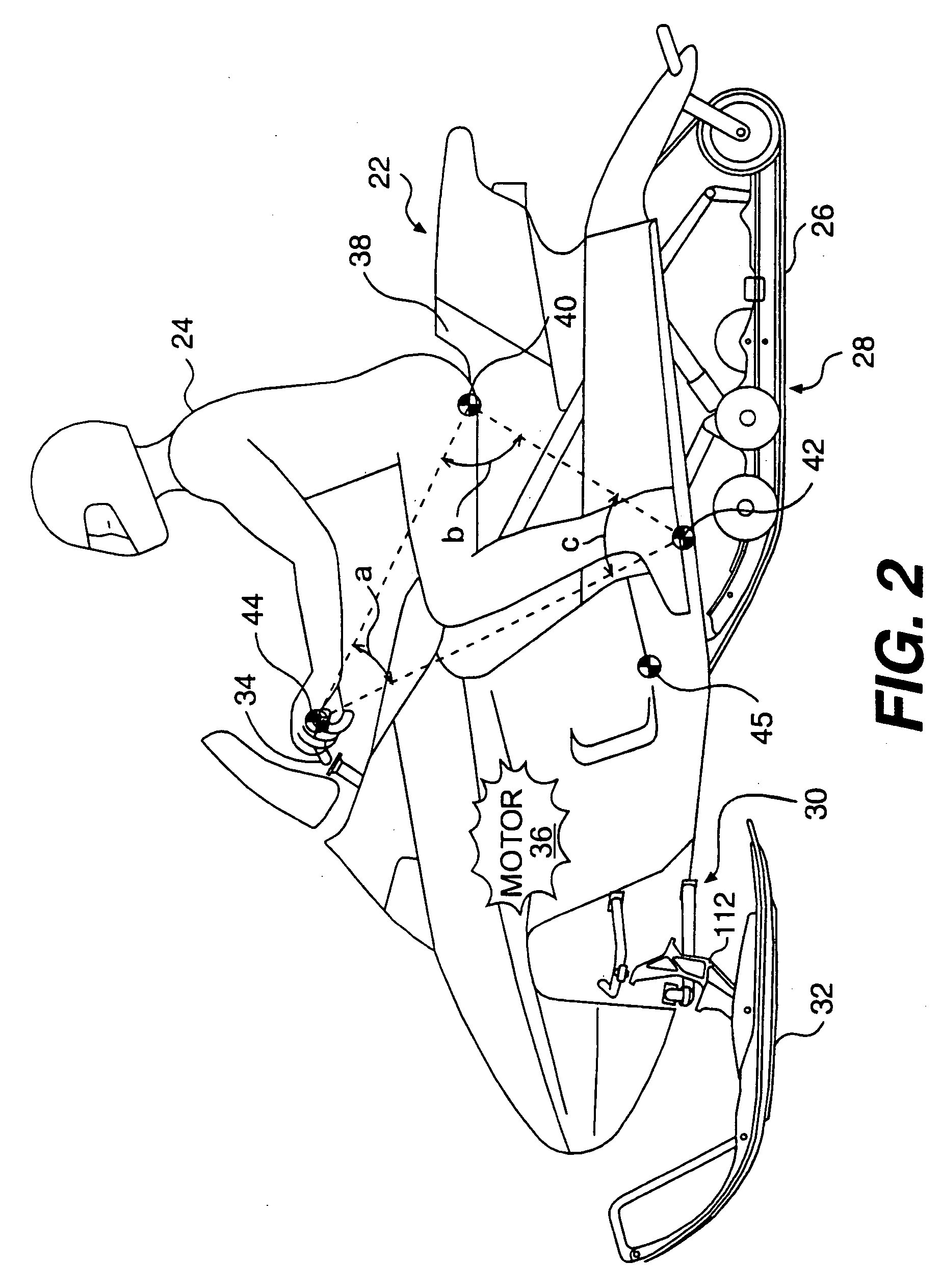
[0056] Before delving into the specific details of the present invention, it should be noted that the conventions “left,”“right,”“front,” and “rear” are defined according to the normal, forward travel direction of the vehicle being discussed. As a result, the “left” side of a snowmobile is the same as the left side of the rider seated in a forward-facing position on the vehicle (or travelling in a forward direction on the vehicle).

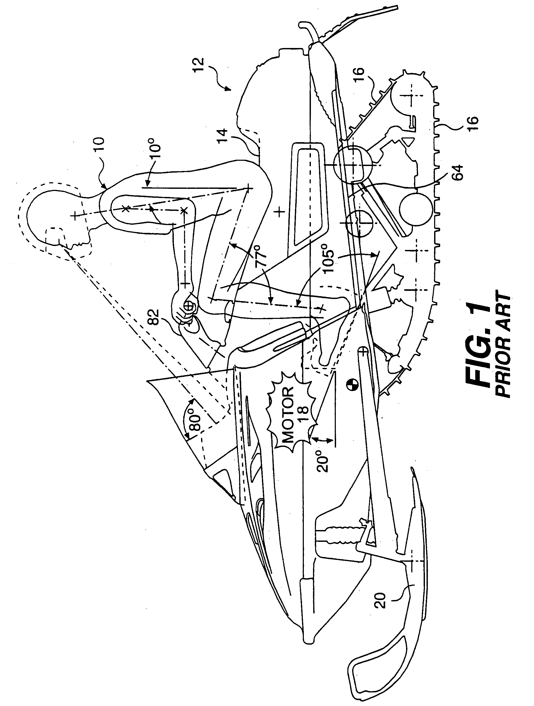
[0057]FIG. 1 illustrates a rider operator 10 sitting on a prior art snowmobile 12. Rider 10 is positioned on seat 14, with his weight distributed over endless track 16. Motor 18 (shown in general detail) is located over skis 20. As with any snowmobile, endless track 16 is operatively connected to motor (or engine) 18 to propel snowmobile 12 over the snow. Motor or engine 18 typically is a two-stroke internal combustion engine. Alternatively, a 4-stroke internal combustion engine may be substituted therefor. In addition, any suitable engine may be substitu...


PUM


Abstract

A frame assembly is described including a tunnel, an engine cradle disposed forward of the tunnel and connected thereto, and a sub-frame disposed forward of the engine cradle and connected thereto. A forward support assembly extends upwardly from the subframe. An upper column extends upwardly from the engine cradle to connect with the forward support assembly. A rear brace assembly extends upwardly from the tunnel to connect with the forward support assembly and the upper column. In one embodiment, the frame assembly further includes an engine disposed in the engine cradle. An endless track is operatively connected to the engine and disposed beneath the tunnel for propulsion. A pair of skis is operatively connected to a steering device for steering. In another embodiment, the frame assembly further includes an engine disposed in the engine cradle. A rear wheel is operatively connected to the engine and disposed beneath the tunnel for propulsion, and two front wheels are operatively connected to a steering device for steering.

Description

[0001] This application is a continuation application of U.S. application Ser. No. 09 / 877,212, filed on Jun. 11, 2001, which is incorporated herein by reference. Through 09 / 877,212, this application claims priority to U.S. application Ser. No. 60 / 237,384, filed Oct. 4, 2000, and is a continuation-in-part of U.S. application Ser. No. 09 / 472,133, entitled “IMPROVED VEHICLE” filed on Dec. 23, 1999, now abandoned, the entire contents of both applications are incorporated herein by reference. Through U.S. application Ser. No. 09 / 472,133, this application claims priority to Canadian Patent Application No. 2,256,944, filed Dec. 23, 1998, the entire contents of which are incorporated herein by reference. The present application also incorporates by reference U.S. application Ser. No. 09 / 472,134, entitled “SNOWMOBILE,” filed Dec. 23, 1999, and U.S. patent application Ser. No. 60 / 230,432, entitled “A NOVEL THREE-WHEELED VEHICLE,” filed Sep. 6, 2000.FIELD OF THE INVENTION [0002] The present in...

Claims


Application Information

Patent Timeline
Patent Type & Authority Applications(United States)
IPC IPC(8): B62J35/00B62K5/04B62M27/02
CPCB62J35/00B62M27/02B62K5/05B62K5/027Y10S180/908
Inventor GIROUARD, BRUNOFECTEAU, BERTHOLDWUBBOLTS, JEROMEDION, ANNE-MARIE
Owner BOMBARDIER RECREATIONAL PROD INC
Learn More