Burn-in testing apparatus and method

a technology of integrated circuits and testing sockets, which is applied in the direction of fault location, heat measurement, and fault increase by increasing the damage at fault, etc., to achieve the effect of reducing avoiding the damage to the integrated circuit, and avoiding the damage to the temperature sensor

Active Publication Date: 2005-09-22
LTI HLDG INC
View PDF7 Cites 41 Cited by
  • Summary
  • Abstract
  • Description
  • Claims
  • Application Information

AI Technical Summary

Benefits of technology

[0013] In a further aspect of the invention, the testing socket can include latches on the socket for quickly releasing the heater / sensor / controller unit from the testing socket base.

Problems solved by technology

Problems can arise during testing, caused by faulty sensors, wires, heaters or a failure of time-phasing between the controller and the sensor and heater.
The direct contact between the temperature sensor can cause damage to the integrated circuit because of the point loading of the relatively small temperature sensor on the integrated circuit when the socket is clamped closed.
Damage to the temperature sensor can also be caused by the direct contact of the integrated circuit to the sensor.

Method used


Image

  • Burn-in testing apparatus and method
  • Burn-in testing apparatus and method
  • Burn-in testing apparatus and method

Examples


Embodiment Construction

A. IC Package Temperature Controlling Device and Method

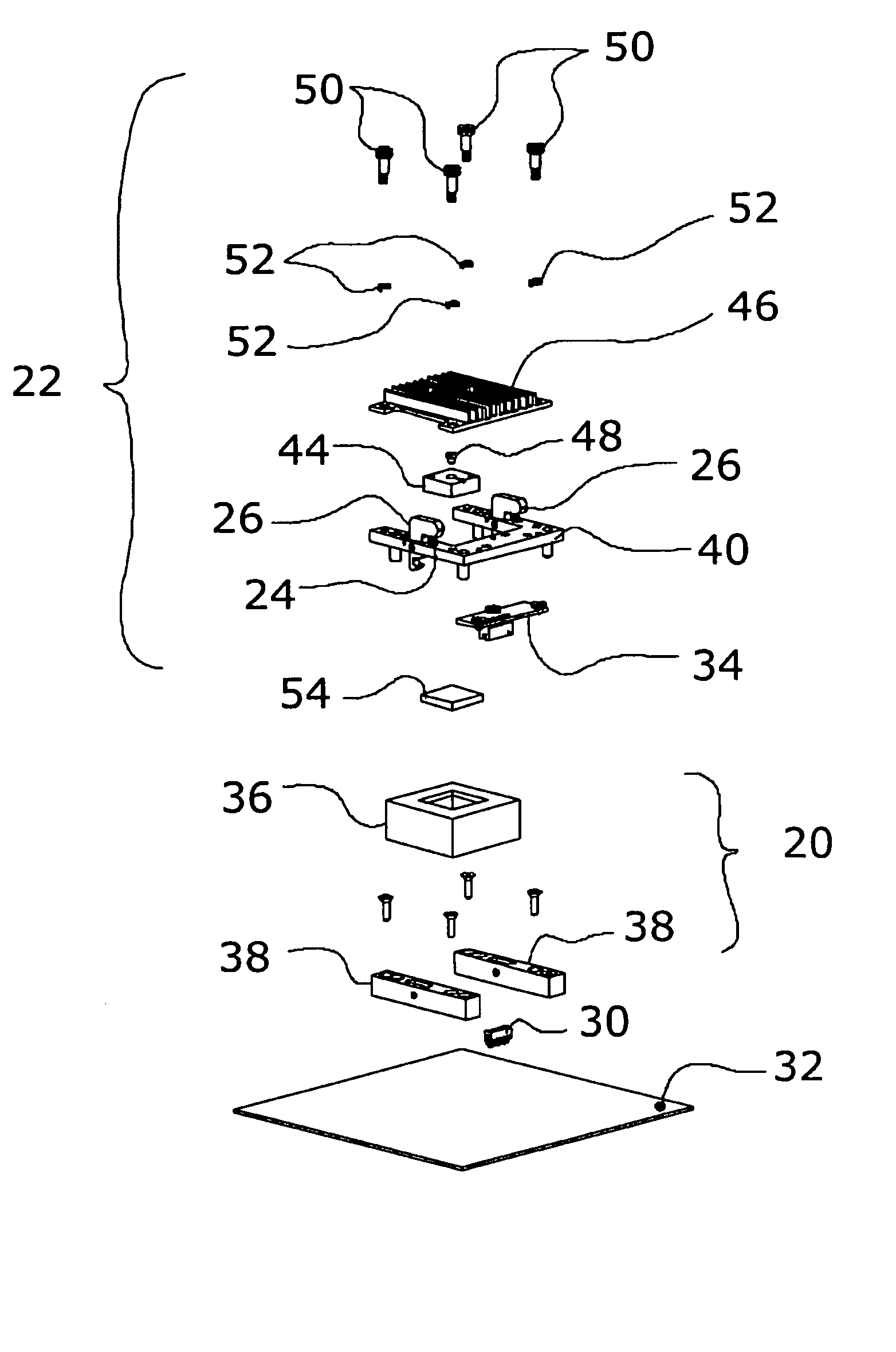
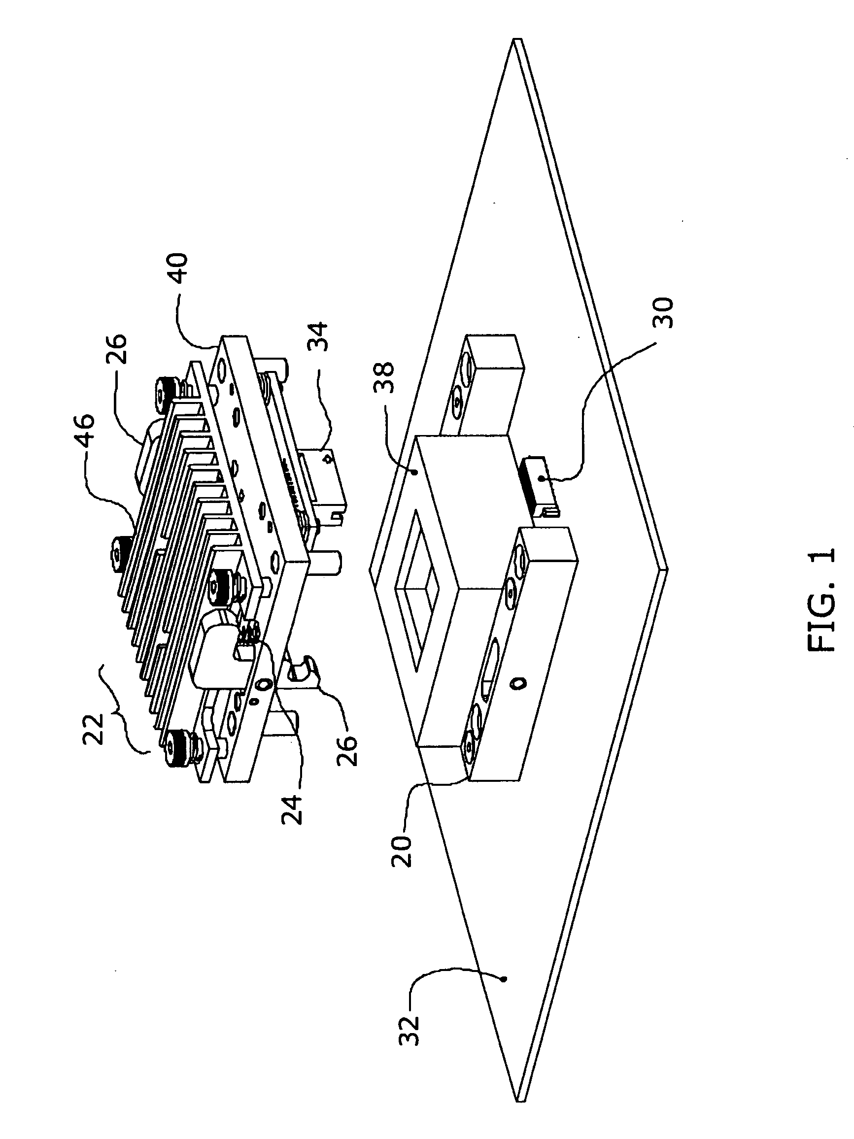
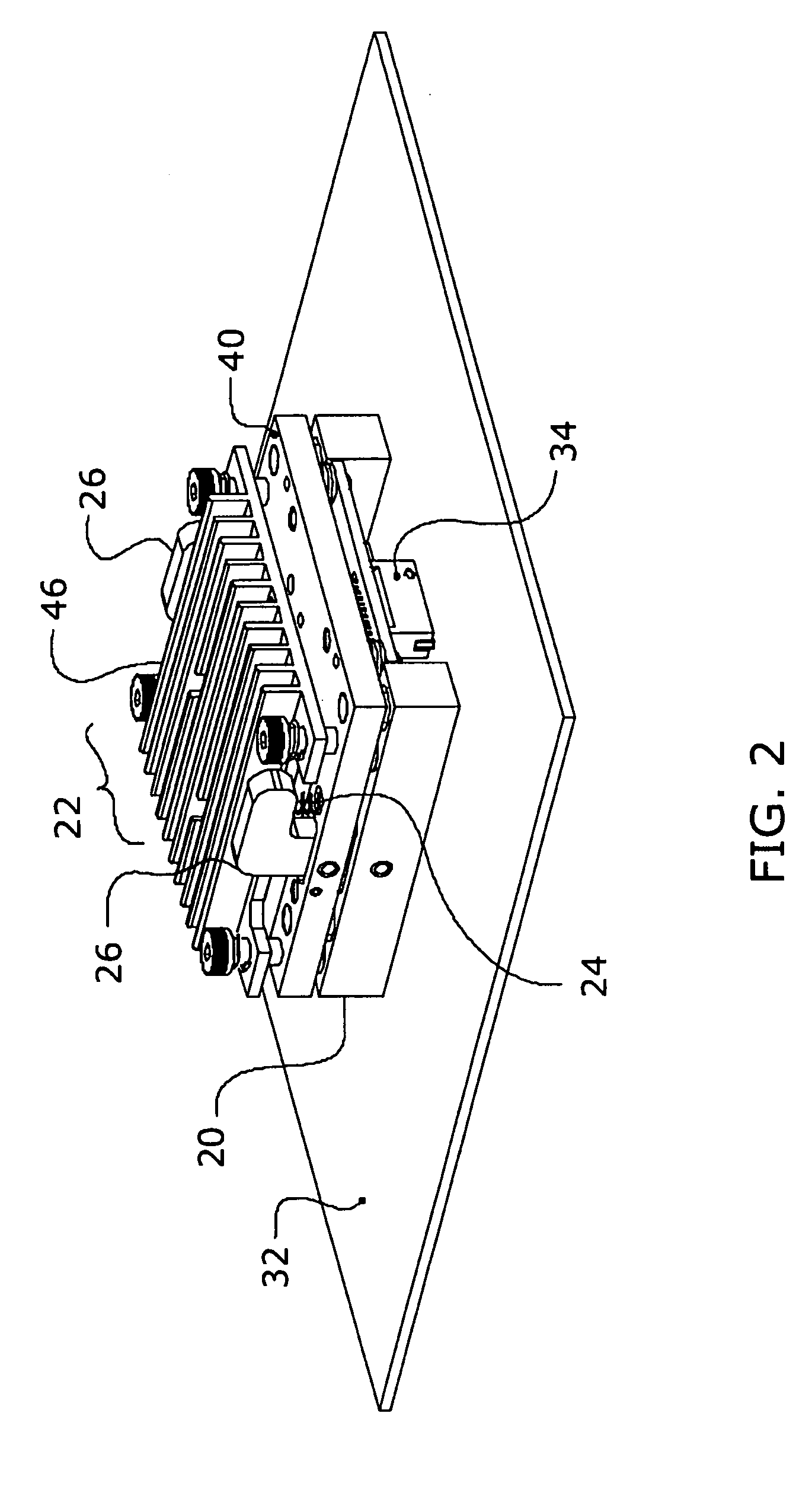
[0031]FIGS. 1 and 2 show perspective views of a testing socket 20 and a modular sensor / heater / controller unit 22 according to an embodiment of the invention. The heater can also be a cooler but hereinafter for simplification will only be referred to as a heater. Springs 24 on latch 26 allow for easy and quick release of the heater unit 22 from the testing socket base 38. FIG. 2 shows the testing socket 20 and modular unit 22 in a closed position where board-side connector 30 located on the testing board 32 receives communication / power connector 34 located on the heater unit 22.

[0032]FIG. 3 shows an exploded perspective view of the testing socket 20, modular unit 22, and testing board 32. The testing socket 20 utilizes a generic open-top socket 36 that is secured to base 38 and base 38 has alignment pins 41 and two latches 26. The modular unit 22 has a guide plate 40 for aligning the modular unit 22 onto the base 38 and board-si...


PUM

PropertyMeasurementUnit
thicknessaaaaaaaaaa
temperatureaaaaaaaaaa
poweraaaaaaaaaa

Abstract

An integrated circuit (IC) package testing apparatus integrates a temperature sensor, heater (or cooler), and controller within a single modular unit. The controller is a microprocessor embedded within the modular unit and in communication with the sensor and heater. The controller allows a selected testing temperature to be input by a user via a communications link to the controller. Each IC package has its testing temperature individually controlled by a controller. The module is easily attached and removed from an open-top socket through the use of latches on the testing socket. Many IC packages can be quickly placed and removed from testing sockets when a matrix of sensors and heaters (or coolers) are located on a single top attach plate with the sensors and heaters (or coolers) individually spring-loaded on the single top attach plate.

Description

RELATED APPLICATION DATA [0001] This application claims priority from U.S. Provisional Application Ser. No. 60 / 548,303, filed 27 Feb. 2004, and is a continuation-in-part of commonly-owned copending application U.S. Ser. No. 10 / 920,531, filed 17 Aug. 2004, the contents of which are herein incorporated by reference in their entirety.FIELD OF THE INVENTION [0002] This invention relates to integrated circuit testing sockets and more particularly to the temperature control of integrated circuits in an integrated circuit testing and / or burn-in socket. BACKGROUND OF THE INVENTION [0003] Integrated circuit (IC) packages must be tested after their manufacture, normally at elevated temperatures, which is typically a burn-in process. During that process, it is often necessary to control the temperature of ICs, sensors, and other elements. Techniques for doing so have been widely practiced for many years. The system normally consists of a heater (or cooler), a temperature sensor, and a comparat...

Claims


Application Information

Patent Timeline
Patent Type & Authority Applications(United States)
IPC IPC(8): G01K1/02G01K1/16G01R1/04G01R31/02
CPCG01K1/16G01R1/0458G01R31/2896G01R31/2874G01R31/2891G01R31/2863
Inventor LOPEZ, CHRISTOPHER A.DENHEYER, BRIAN J.KUENSTER, GORDON B.
Owner LTI HLDG INC
Why Eureka
Try Eureka