Graft delivery and anchoring system

a technology of graft and graft wall, which is applied in the direction of nails, staples, dilators, etc., can solve the problems of not providing graft fixation on blood vessel walls, but providing graft delivery

Inactive Publication Date: 2005-09-22
SHIFRIN EDWARD
View PDF2 Cites 27 Cited by
  • Summary
  • Abstract
  • Description
  • Claims
  • Application Information

AI Technical Summary

Benefits of technology

[0044] The claimed device for graft delivery has at least one control lever used to control the process of delivering grafts within an operated blood vessel as well as to operate the actuators of proximal head and distal head. The control lever contains a hollow body having a proximal end, distal end with a perpendicular slot and a longitudinal axial duct wherefrom within the body, near its distal end there extend, at an acute angle, two additional ducts. All these ducts extend within the perpendicular slot. There is also a bush with a shank at its proximal end and with a through axial hole located at the body proximal end. Within the longitudinal axial duct of the body there is disposed a spring-loaded pusher with a through axial hole and two longitudinal slots which are open in opposite directions. This spring-loaded pusher is disposed so as to reciprocate within the longitudinal axial duct of aforesaid body, provided with a lock and operatively connected via an additional hold-down element with the actuator of said distal head. The control lever also has a curved L-shaped lever pivotally secured by the middle of its short arm in perpendicular slot of said body and provided with a first and second pivot pin at the ends of this short arm. The first pivot pin adjoining the long arm of L-shaped lever is operatively connected with the spring-loaded pusher, whereas the second pivot pin is operatively connected with at least one flexible control lever passing via through axial holes of proximal and distal head, intermediate, additional tube and spring-loaded pusher and operatively connecting the actuators of proximal and distal head with the control lever.
[0045] The claimed device has at least one flexible control element passing via through axial holes of proximal, distal head, intermediate, additional tube and spring-loaded pusher and and operatively connecting actuators of proximal and distal head with a control lever. This flexible control lever may be formed substantially as a wire, thin cord or plastic thread.
[0046] The additional hold down element operatively connecting the spring loaded pusher of control lever with distal head actuator is connected therewith by its corresponding ends and is shaped as a tube member being rigid in longitudinal direction and relatively flexible in lateral directi

Problems solved by technology

Both devices described above provide graft delivery but do not

Method used


Image

  • Graft delivery and anchoring system
  • Graft delivery and anchoring system
  • Graft delivery and anchoring system

Examples


Embodiment Construction

[0063] The preferred embodiments of the present invention are described below. The inventors of the present subject matter contemplate that the embodiments described herein are capable of use in the repair of blood vessels and in other procedures. Thus, it is intended that the present invention cover the modifications and variations of the invention, provided they come within the scope of the appended claims and their equivalents.

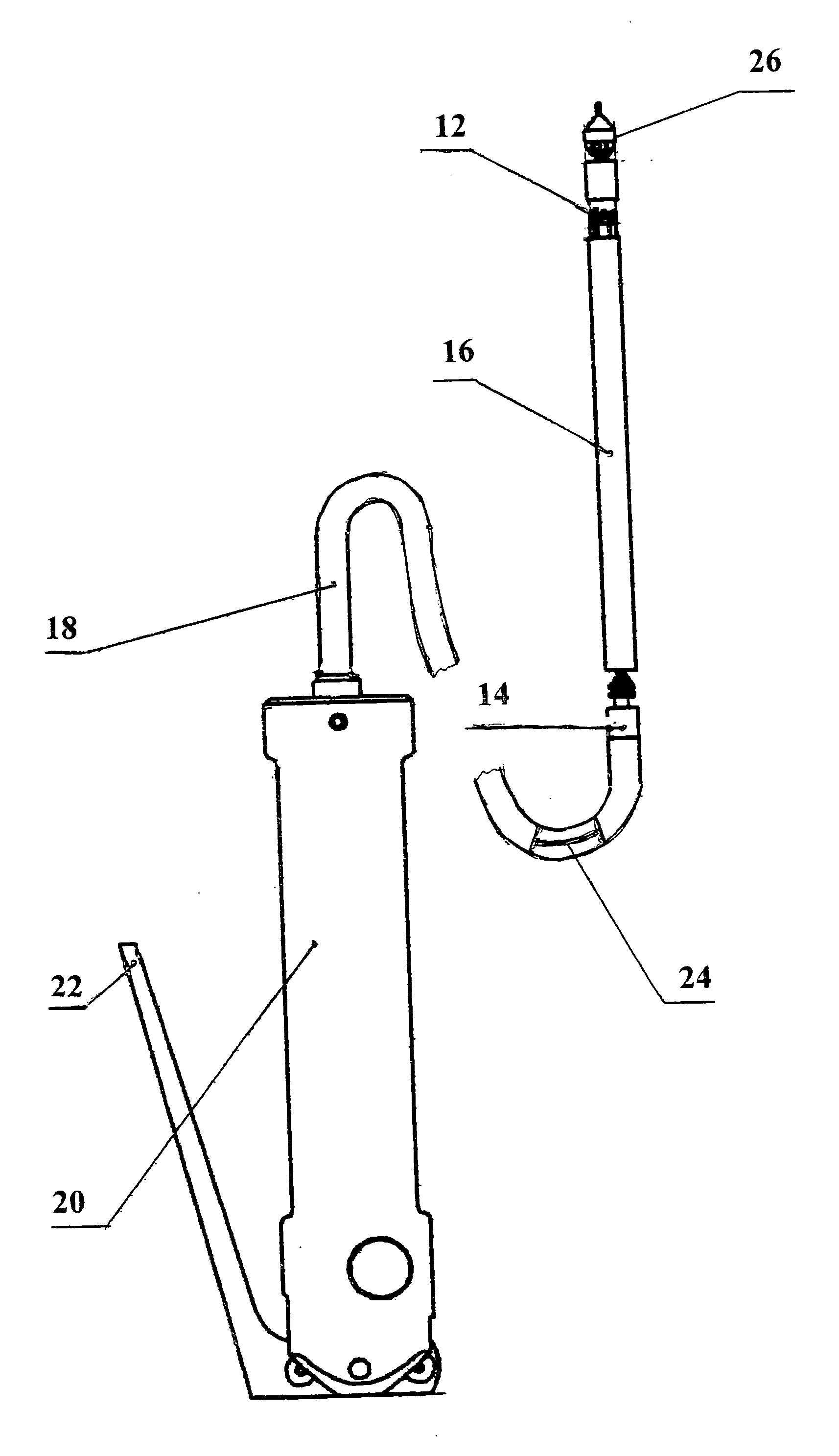
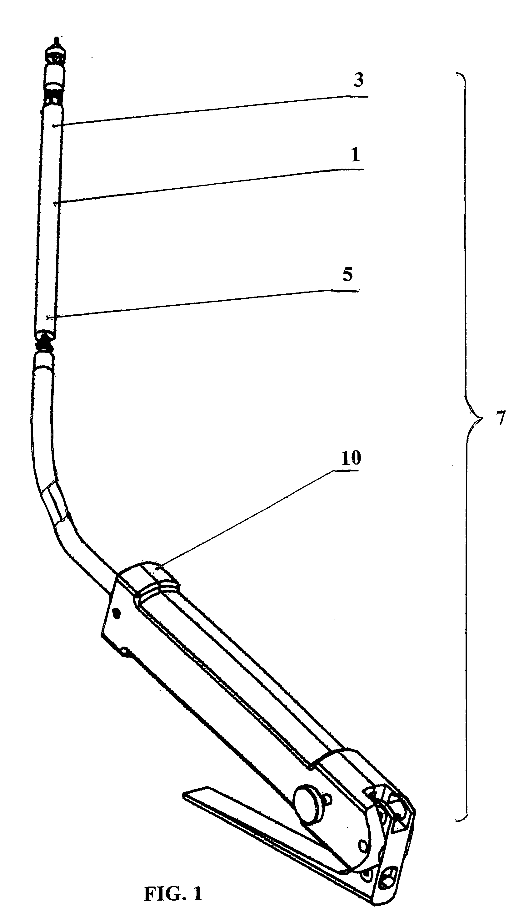
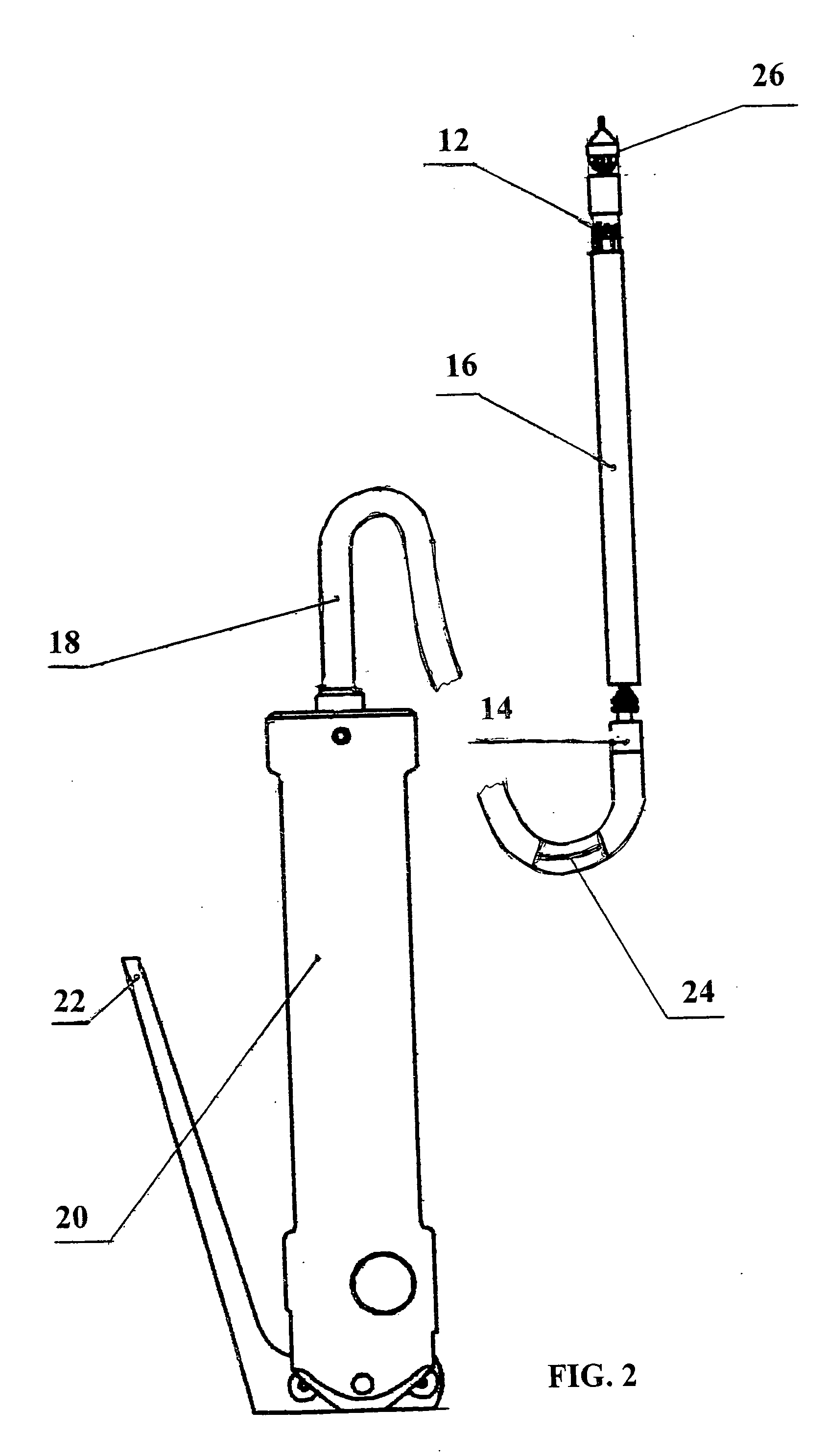
[0064] The most preferred embodiments of a delivery system, according to the present invention, are shown in drawing FIGS. 1-27.

[0065] The claimed system for delivering and anhoring a graft of individual dimensions (FIGS. 1, 2) comprises: a) graft 1 shaped as a tube from biologically compatible material and having a proximal 3 and distal 5 end, as well as b) a set of assembly units 7 for its assembly on the basis of at least one device 10 for delivering graft 1 within a recipient's blood vessel and simultaneously securing this graft 1 on both its sides to...


PUM

PropertyMeasurementUnit
Lengthaaaaaaaaaa
Diameteraaaaaaaaaa
Flexibilityaaaaaaaaaa

Abstract

The present invention relates to methods and apparatus for the repair of blood vessels, using a novel prosthetic graft within the blood vessels. The more concrete, the present invention relates to devices and methods for delivering and stapling endovascular grafts to the blood vessel wall. A subject of the present invention is a system and method for delivering and anchoring a graft of individual dimensions within a recipient's blood vessel. This system comprises: a) a graft configured as a tube from biologically compatible material the individual dimensions whereof, such as the diameter and length are defined by clinical state of the recipient and results of angiographic dimensions of its operated blood vessel, and b) a set of assembly units for assembling on its basis at least one device for delivering a graft and simultaneously securing this graft at both its ends to the blood vessel wall. The suggested set of assembly units includes: at least one proximal head and at least one distal head which serve to hold the graft in the process of its delivery within the blood vessel, and for securing its proximal and distal end to the wall of an operated blood vessel. The proximal and distal heads have a through axial hole with an actuator therein, as well as means for holding a corresponding graft end and means for securing this graft end to the blood vessel wall. Besides, the suggested set of assembly units includes at least one intermediate tube, at least one control means, at least one additional hold-down element, and at least one flexible control element.

Description

BACKGROUND OF THE INVENTION [0001] 1. Field of the Invention [0002] The present invention relates to methods and apparatus for the repair of blood vessels, using a novel prosthetic graft within the blood vessels. In particular, the present invention relates to devices and methods for delivering and stapling endovascular grafts to the blood vessel wall. [0003] 2. Description of Related Art [0004] Surgical treatment of some diseases of the circulatory system is often connected with the use of a prosthesis-artificial blood vessel which is integrated into the circulatory system to prevent from rupture or completely replace the recipient's injured vessel. Here the surgeon is faced by a problem: to provide a joint member for an artificial blood vessel which can keep enough reliability and rigidity and can be integrated naturally with the recipient's blood vessel and can decrease leakage of blood from the joint part between the recipient blood vessel and the artificial blood vessel when th...

Claims


Application Information

Patent Timeline
IPC IPC(8): A61B17/064A61B17/068A61B17/115A61F2/06
CPCA61B17/0644A61B17/068A61F2/06A61B17/1155A61B17/115
Inventor SHIFRIN, EDWARD G.NICKELSHPUR, GENNADYIDOV, VLADIMIR
Owner SHIFRIN EDWARD
Why Eureka
Try Eureka