

Lens attachment combined with formation of goggles frame
- Summary
- Abstract
- Description
- Claims
- Application Information
AI Technical Summary
Benefits of technology
Problems solved by technology
Method used
Image

Examples
first embodiment
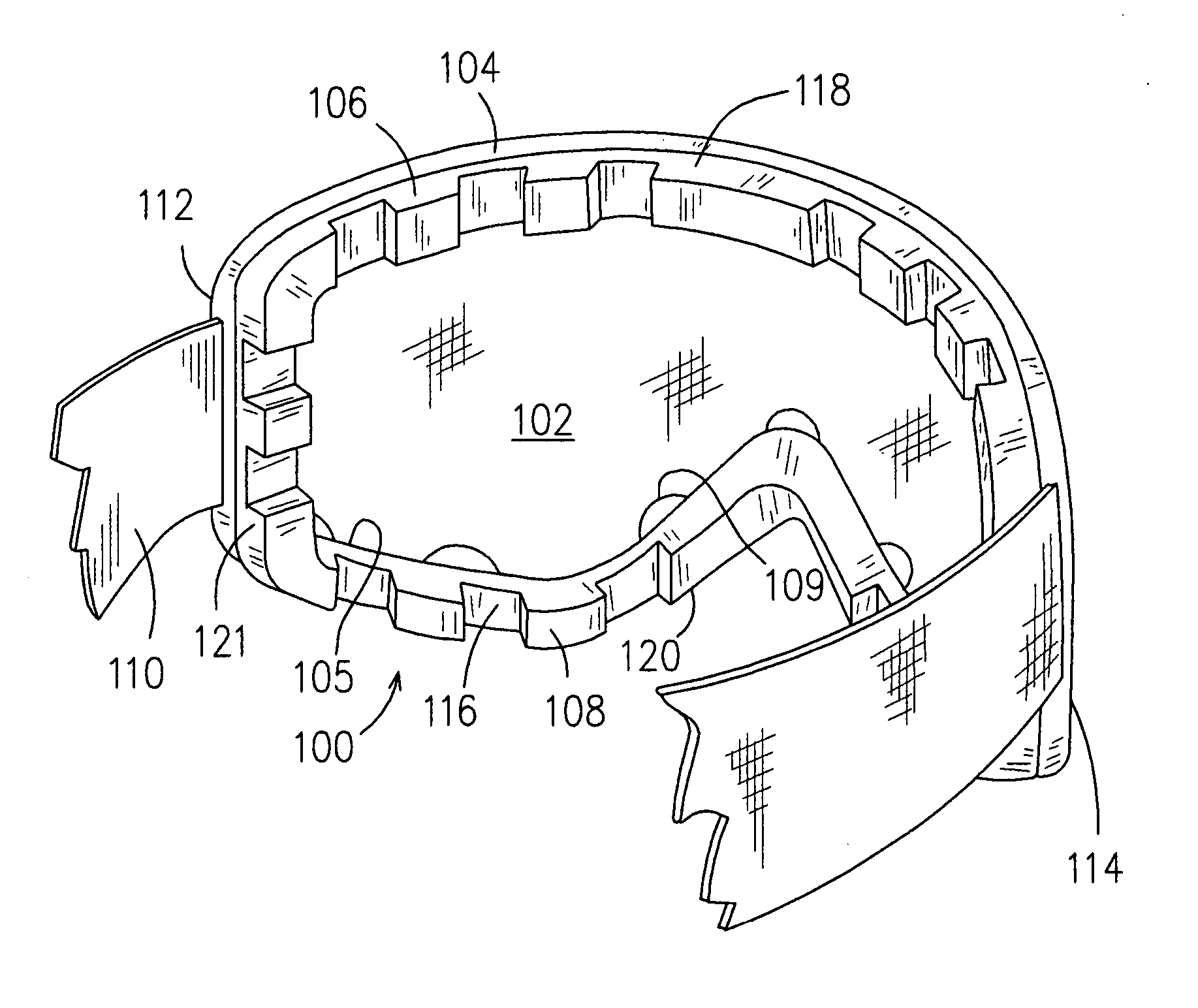
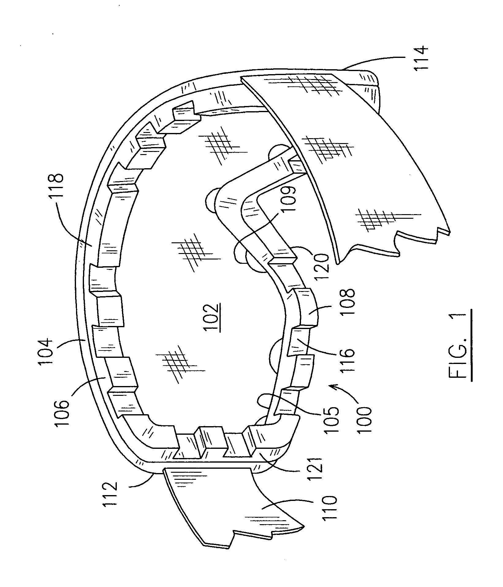
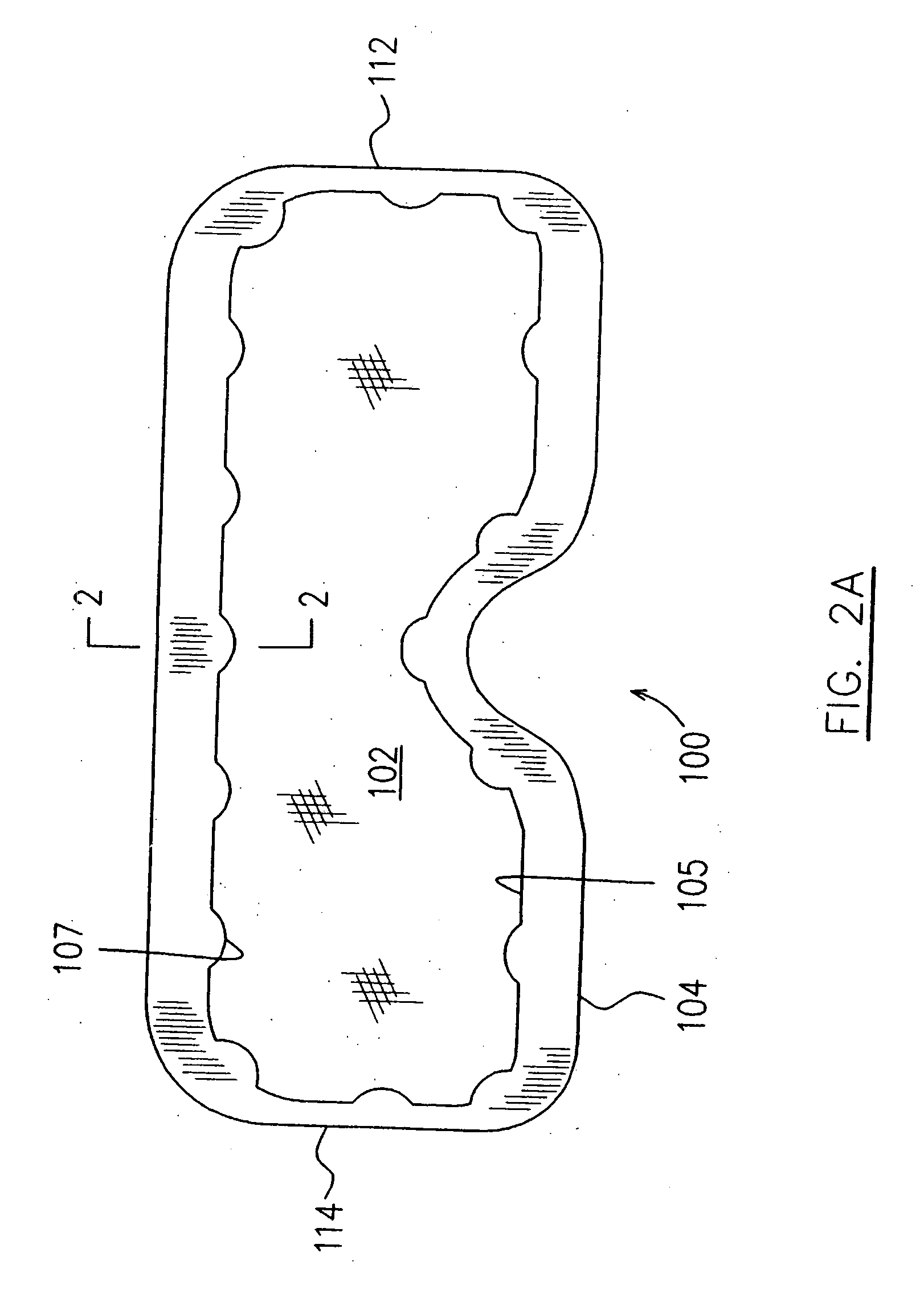
[0033]FIGS. 1 and 2A-2E illustrate goggles having ventilation such as protective goggles, indicated by numeral 100, in accordance with the present invention. The goggles 100 is used as an example to illustrate one embodiment of the present invention. Nevertheless, any other type of goggles which includes substantially rigid plastic frame bodies and substantially rigid lenses, and which defines ventilation passages therewith in various ways, is included in the concept of the present invention as illustrated by the embodiment 100 and in further embodiments to be described hereinafter.
[0034] The goggles 100 includes a single lens 102 which is made of glass or substantially rigid transparent plastic, a frame body 104 defining an aperture 105 receiving the single lens 102 therein, and a shielding member 106 contoured for shielding the eyes of a user. The frame body 104 is made of a substantially rigid plastic material and includes a plurality of retaining members 107 and 109 for securing...
second embodiment
[0043]FIGS. 3A-3C illustrate the present invention in which goggles 200 having ventilation is similar to the goggles 100 of FIGS. 2 and 2A. The components of goggles 200 are indicated using numerals in the 200 series with the last two digits corresponding to similar components in the 100 series illustrated in FIGS. 2 and 2A, and will not therefore be redundantly described. The embodiment shown in FIG. 3A is a further development of the embodiment shown in FIGS. 2 and 2A. When the retaining members 107 and 109 of the eye glasses 100 (as shown in FIGS. 2A and 2B), are connected adjacent to one another in each of the first and second groups, these retaining members substantially form opposed continuous side walls 207, 209 extending into an aperture 205 of the goggles 200, thereby defining a continuous channel therebetween (not indicated). The continuous channel defined between opposed side walls 207, 209 is configured to correspond to the periphery of a single lens 202 for receiving th...
fourth embodiment
[0051]FIGS. 5 and 6A-6E illustrate the present invention in which goggles having ventilation, generally designated by reference numeral 400, includes a frame structure 402 having two frame bodies 404, 406, with a bridge 408 connected between an inner side of the frame bodies 404, 406, and also includes a pair of lenses 410 and 412 received and affixed in apertures 414 and 416 which are defined in the respective frame bodies 404, 406. The attachment of the lenses 410, 412 to the respective frame bodies 404, 406 will be further described hereinafter. A pair of temples 418 and 420 are pivotally mounted to opposed sides 422, 424 of the frame structure 402 by means of a hinge assembly 426 (only one shown) which is well known in the art and will not be described herein. A plurality of contacting ribs 428 are provided on the inner side at the free end of the temples 418, 420 for comfortably holding the goggles 400 on the user's head when the goggles 400 is worn. An aperture 430 is also pro...
PUM
| Property | Measurement | Unit |
|---|---|---|
| Diameter | aaaaa | aaaaa |
| Structure | aaaaa | aaaaa |
| Size | aaaaa | aaaaa |
Abstract
Description
Claims
Application Information