Air water closet

a technology for air-conditioning closets and closets, which is applied in water installations, lavatory sanitory, constructions, etc., can solve the problems of ineffective ventilation of an entire room using a ventilator in the ceiling or in the toilet wall to exhaust air, and the process becomes too complex and technically too complex, so as to achieve effective elimination of the spread of foul odor and energy saving

Inactive Publication Date: 2005-09-29
SUSTAR ROZANA
View PDF2 Cites 3 Cited by
  • Summary
  • Abstract
  • Description
  • Claims
  • Application Information

AI Technical Summary

Benefits of technology

[0005] Slovenian Patent No. SI 21277 describes a solution for the direct elimination of the foul odor by sucking air from the seat or cover of the water closet with the removal of a minimal volume of air effectively eliminating the spread of the foul odor and of micro-organisms within the room while saving energy. One problem remaining unsolved is related to the sucking of air through two tubes from the seat of the water closet, where the volume of air to be removed is relatively high, but where the effectiveness of sucking the air away is relatively low, because of the disproportional and unsymmetrical disposal of both tubes in water closet vertex. Other problems remaining unsolved by sucking air from the seat of water closet arise from the facts that the seat must be too thick and that it becomes impossible to use a protective cover on the seat for hygienic reasons without reducing the effectiveness of the system of sucking air to remove the foul odor.

Problems solved by technology

The ventilation of an entire room using a ventilator in the ceiling or in on a toilet wall to exhaust air is often ineffective due to the considerable volume of the space being exhausted without an inward flow of fresh air.
When these known solutions are combined with ventilation and filtration of the air in the water closet, the process becomes technically too complex, with ventilation machines requiring space in or on the water closet for fitting up and operation.
One problem remaining unsolved is related to the sucking of air through two tubes from the seat of the water closet, where the volume of air to be removed is relatively high, but where the effectiveness of sucking the air away is relatively low, because of the disproportional and unsymmetrical disposal of both tubes in water closet vertex.
Other problems remaining unsolved by sucking air from the seat of water closet arise from the facts that the seat must be too thick and that it becomes impossible to use a protective cover on the seat for hygienic reasons without reducing the effectiveness of the system of sucking air to remove the foul odor.

Method used


Image

  • Air water closet
  • Air water closet
  • Air water closet

Examples


Embodiment Construction

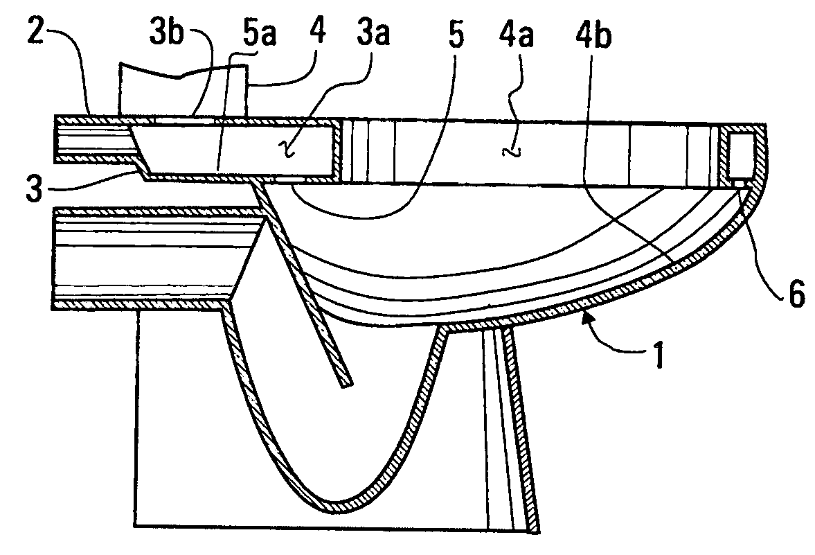
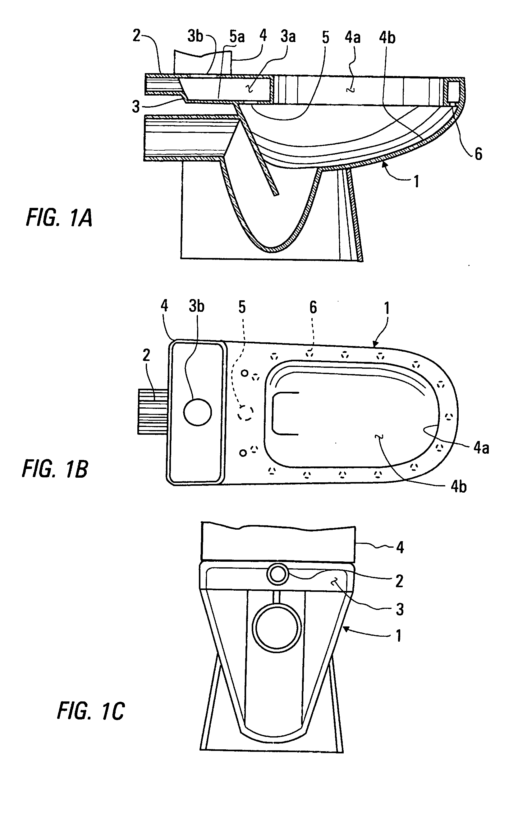
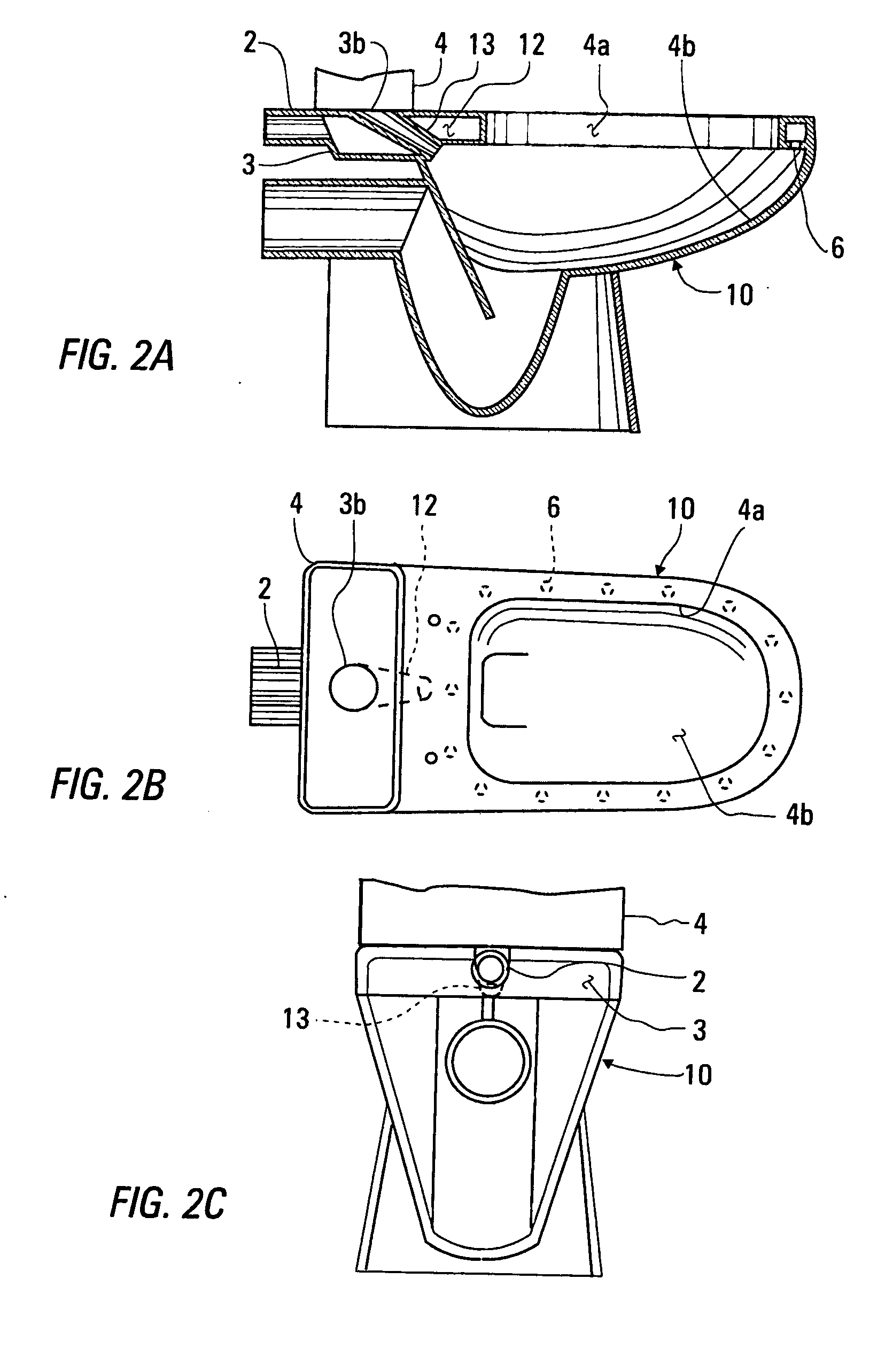
[0025] The three embodiments of the figures have a number of common elements, which are therefore accorded like reference numbers. Furthermore, each of the three embodiments includes a suction channel for sucking air from a bowl of the water closet to eliminate a foul odor and a rinsing channel providing water to rinse the bowl.

[0026] A water closet 1, built in accordance with the first embodiment of the invention will now be discussed, with reference being made to FIGS. 1A, 1B, and 1C, of which FIG. 1A is a longitudinal cross-sectional view, FIG. 1B is a plan view, and FIG. 1C is a rear elevation. According to the first embodiment, the suction and rinsing channels have common portions. The suction channel includes an exhaust tube 2 extending from the back portion 3 of the water closet opening into a first compartment 3a, which is shared with the rinsing channel to be used for rinsing the water closet 1, with water entering the compartment 3a through an aperture 3b from a tank 4. T...


PUM


Abstract

An air water closet includes a suction channel to remove air having a foul odor from a bowl of the water closet, with the air being removed through a first compartment, extending around the rim at the top of the bowl, through holes in the bottom surface of this compartment. A rinsing channel is also provided for rinsing the bowl. Air is removed through the operation of an exhaust fan, which may be turned on and off using an electric switch, or which may be turned on whenever the proximity of a person near the water closet is detected.

Description

BACKGROUND OF THE INVENTION [0001] 1. Field of the Invention [0002] This invention relates to apparatus for preventing the spread of foul odors and various germs causing illness when a toilet or water closet is used to satisfy a basic physical need of a person for elimination of waste, and, more particularly, to such apparatus eliminating foul odors by sucking air from a bowl of a water closet. [0003] 2. Summary of the Background Art [0004] Known solutions related to the elimination of foul odors and germs causing illness when a person satisfies a basic physical need for elimination of waste mostly rely on the ventilation of an entire toilet room, or on the rinsing, filtration, cleaning, and disinfecting of the water closet, etc. The ventilation of an entire room using a ventilator in the ceiling or in on a toilet wall to exhaust air is often ineffective due to the considerable volume of the space being exhausted without an inward flow of fresh air. Rinsing, cleaning and disinfectin...

Claims


Application Information

Patent Timeline
Patent Type & Authority Applications(United States)
IPC IPC(8): E03D9/04E03D9/05
CPCE03D9/05
Inventor SUSTAR, ROZANA
Owner SUSTAR ROZANA
Why Eureka
Try Eureka