Parallel signal transmission device

a transmission device and parallel signal technology, applied in the direction of duplex signal operation, code conversion, baseband system details, etc., can solve the problems of increasing the proportion of skew to the data period and the inability to perform normal processing

Inactive Publication Date: 2006-05-30
FUJITSU LTD
View PDF6 Cites 26 Cited by
  • Summary
  • Abstract
  • Description
  • Claims
  • Application Information

AI Technical Summary

Benefits of technology

[0015]Thus, the data outputted from the clock recovery portions DCR1-DCRN have dispersed data positions as shown in FIG. 4A, namely, skew states. Therefore, the bit changeover portion 32 changes over the bits of the N-parallel signals with the reference clock as shown in FIG. 4B, thereby eliminating shifts along the time axis before transmitting to the variable delay portion 34. It is to be noted that serial latch code signals (see FIG. 3D) outputted from the clock recovery portion DCRLT also have their bits changed over at the bit changeover portion 32.
[0031]Thus, the receiving unit 3 performs the clock recovery to the scrambled data, thereby stabilizing the clock recovery operation and improving the performance thereof.
[0035]Thus, the resetting is performed per each latch timing signal, so that even if the data are erred in the transmission line 2, their influence on other sampling data is suppressed, thereby stabilizing the operation of the clock recovery portion.
[0038]In order to avoid this fact, in the present invention (4), the parallel number “N” comprises a prime number, that is “5” in this example. Thus, for example, data A8 (A8-1-A8-7) shown by boldface characters are transmitted randomly through five parallel signal lines, as seen from comparing FIGS. 10A and 10C. Therefore, even if the data A8 are the fixed data, transmission on fixed signal lines is eliminated, thereby stabilizing the operation of the clock recovery portion and contributing to the performance improvement thereof.
[0042]Therefore, data of different timings are latched each time, so that even if the data are periodic, the data of different timings are latched per frame, thereby avoiding the miss detection due to fixed bits in the bit shift detector 33.

Problems solved by technology

For example, in an integrated circuit (IC), the period of parallel transmission data has been extremely shortened, so that the proportion of skew to the data period is increased, and the parallel data along time axis are misaligned in phase, thereby causing a problem that a normal processing cannot be performed.

Method used


Image

  • Parallel signal transmission device
  • Parallel signal transmission device
  • Parallel signal transmission device

Examples


Embodiment Construction

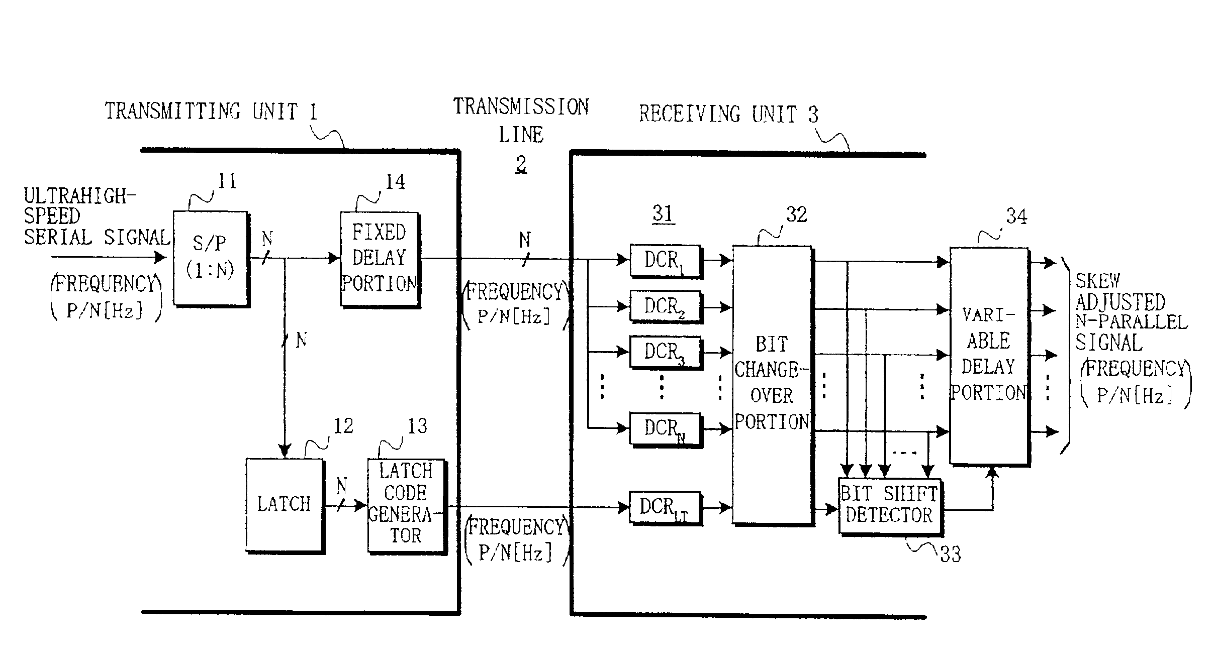
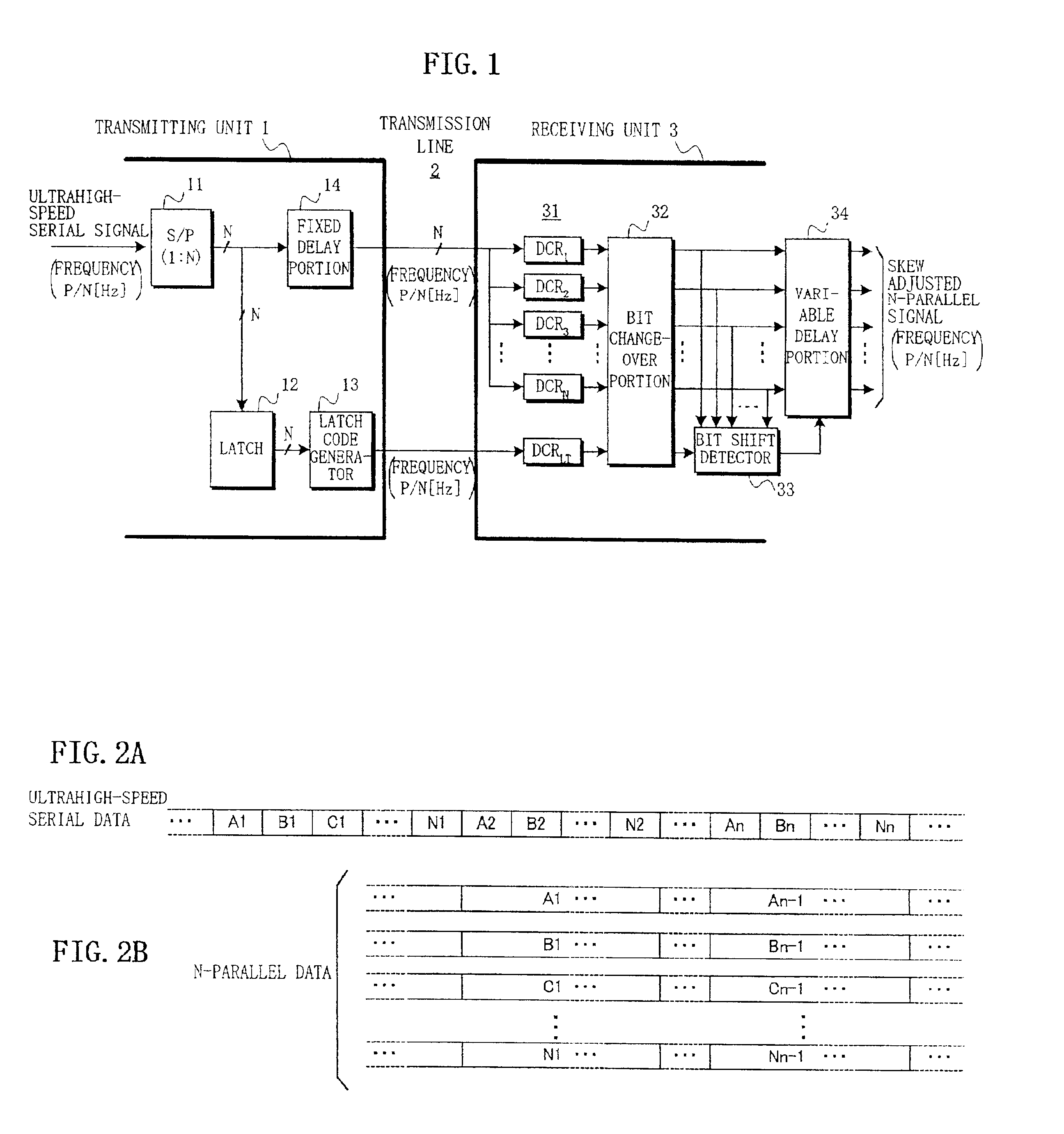
[0067]FIG. 12 shows an embodiment of the parallel signal transmission device according to the present invention (1) schematically shown in FIG. 1. In this embodiment, input serial signals of 40 GHz ultrahigh-speed serial signals are converted into N=16 parallel signals to be serviced, and the clock recovery portion 31 corresponding thereto is composed of 16 clock recovery portions DCR1-DCR16. Also, operation time charts shown in FIGS. 13A, 13B, 14A-14D, 16A, 15B, and 16A-16F respectively correspond to the time charts shown in FIGS. 2A, 2B, 3A-3D, 4A, 4B, and 5A-5F.

[0068]In the transmitting unit 1, the serial-parallel converter 11 firstly converts the 40 GHz ultrahigh-speed serial signals shown in FIG. 13A into 16-parallel signals shown in FIG. 13B to be transmitted to the latch (circuit) 12 and the fixed delay portion 14.

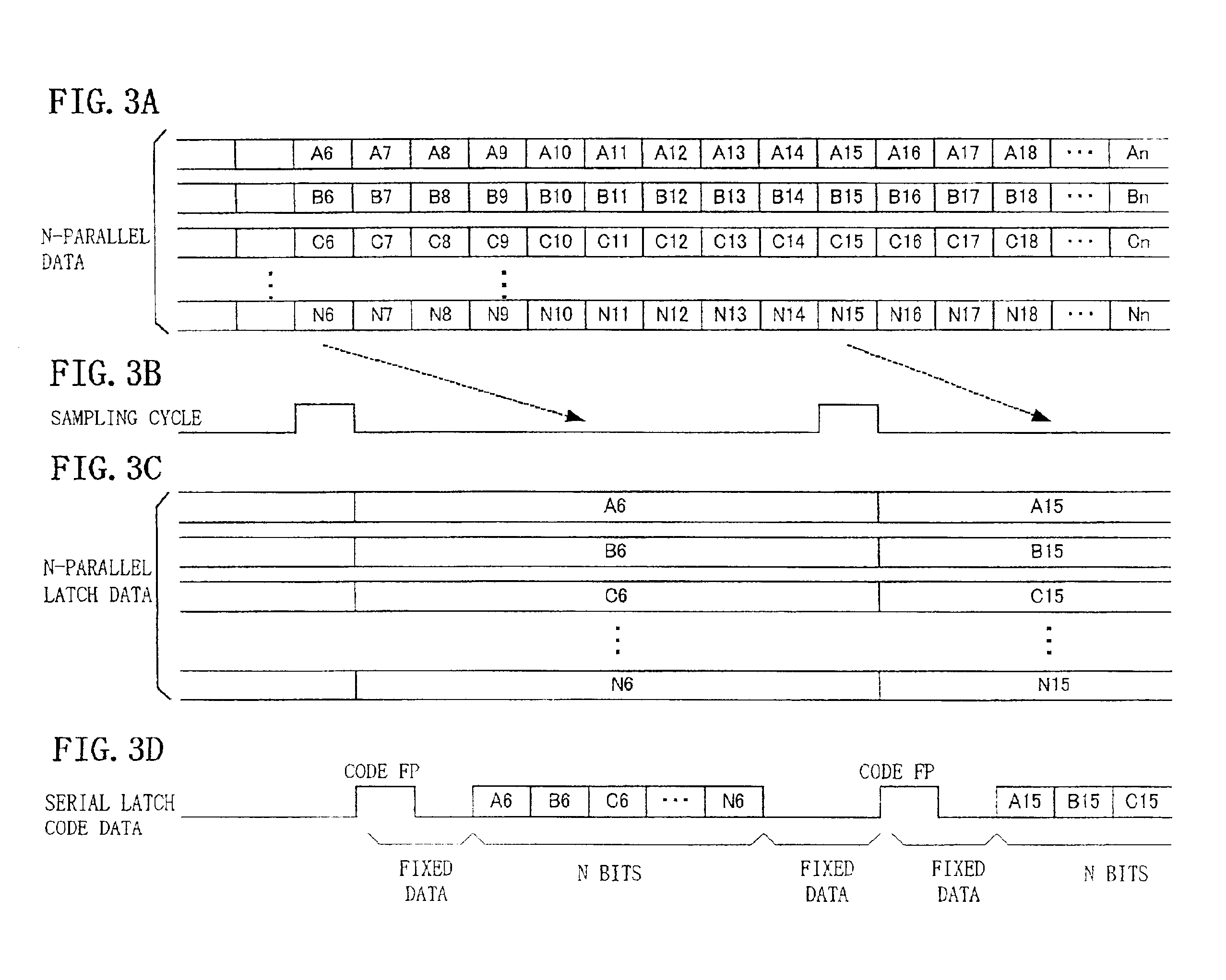
[0069]The latch 12 generates 16-parallel signals shown in FIG. 14C by a sampling period shown in FIG. 14B to be transmitted to the latch code generator 13. The latc...


PUM


Abstract

In a parallel signal transmission device for converting serial signals into parallel signals at a transmitting unit to be transmitted to a receiving unit, the transmitting unit generates serial code signals from periodically latched parallel signals besides transmitted parallel signals, and adjusts phases of the parallel signals to the serial code signals by delaying the parallel signals by a predetermined delay time; and the receiving unit changes over bits of the parallel signals from the transmitting unit based on recovered clocks, detects bit shift amounts of the parallel signals after bit changeover, and performs skew adjustments of the parallel signals depending on the bit shift amounts.

Description

BACKGROUND OF THE INVENTION[0001]1. Field of the Invention[0002]The present invention relates to a parallel signal transmission device, and in particular to a parallel signal transmission device converting serial signals into parallel signals at a transmitting unit to be transmitted to a receiving unit.[0003]When parallel signals converted from serial signals are transmitted from a transmitting unit to a receiving unit using a plurality of signal lines, the receiving unit cannot perform a normal parallel signal processing due to skews, i.e. dispersion of data phases, generated on individual signal lines. Therefore, some skew adjustments (phase adjustments) are required.[0004]2. Description of the Related Art[0005]In a prior art transmission device using parallel signal lines, the period of transmission data is long enough compared to generated skews. Therefore, there has been adopted a technique of providing a simple delay circuit between the transmitting unit and the receiving unit...

Claims


Application Information

Patent Timeline
Patent Type & Authority Patents(United States)
IPC IPC(8): H04L7/00H03M9/00H04L1/22H04L25/14
CPCH04L25/14
Inventor KADA, KAZUHISASHIMONO, HIROYUKISUZUKI, TERUHIKOMIYAKE, SHUJI
Owner FUJITSU LTD
Why Eureka
Try Eureka