Non-fire-worker-driven two-stage compressing releasing mechanism

A release mechanism, non-pyrotechnic technology, applied in the direction of motor vehicles, space navigation equipment, space navigation aircraft, etc., can solve the problems of mismatching driving force, failure of normal release of mechanism, performance degradation of SMA wire, etc.

Active Publication Date: 2018-07-20
北京深空动力科技有限公司
View PDF6 Cites 25 Cited by
  • Summary
  • Abstract
  • Description
  • Claims
  • Application Information

AI Technical Summary

Problems solved by technology

[0004] (1) The integral rigid locking part is adopted, which easily transmits the bending moment to the inside of the mechanism, affects the matching relationship of the internal parts, and reduces the reliability of unlocking and releasing;
[0005] (2) The control of the pre-tightening force in the assembly process depends on the torque wrench, and the error is as high as 30%, which is easy to cause overload and damage the structural parts;
[0006] (3) Use ordinary steel springs and SMA wires to form a biased drive. Under high temperature conditions, the stiffness and elasticity of the steel springs will decrease slightly, while the driving force of the SMA wires will increase significantly, resulting in spring tension and The driving force of the SMA wire does not match, resulting in a serious decline in the anti-vibration performance of the mechanism in a high-temperature environment;
[0007] (4) Only one SMA wire is used as the driving element, there is no redundant backup, and the reliability is not high;
[0008] (5) Lack of a feedback circuit. Since the heating time of the SMA wire varies with the current and the ambient temperature, the precise power-on time cannot be given in advance. In actual engineering applications, the power-on time is too short, and the mechanism cannot be released normally. If the time is too long, the performance of SMA wire will be seriously degraded, or even burned;
[0009] (6) There is no self-adaptive rotation structure inside the mechanism, and it cannot be adaptively rotated according to changes in the external loading direction, which requires strict installation accuracy

Method used


Image

  • Non-fire-worker-driven two-stage compressing releasing mechanism
  • Non-fire-worker-driven two-stage compressing releasing mechanism
  • Non-fire-worker-driven two-stage compressing releasing mechanism

Examples


Embodiment Construction

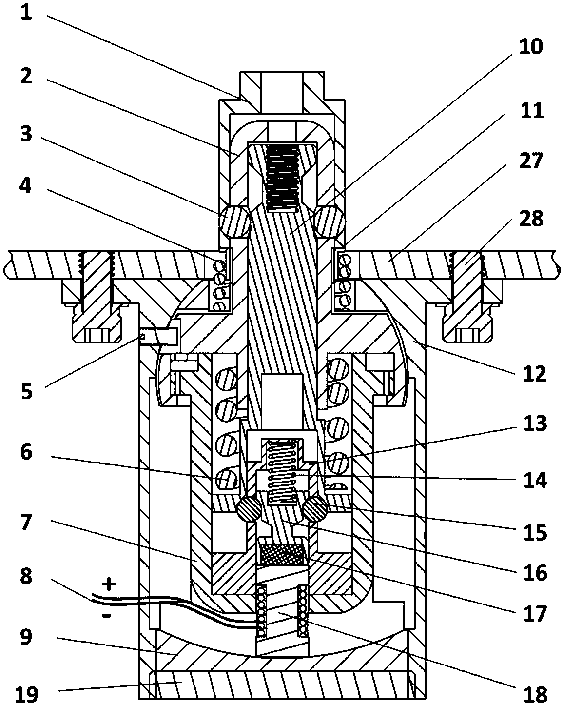
[0040] The drive mode of the slider in the present invention is non-pyrotechnic drive, and different drive elements such as electromagnetic drive, paraffin drive, SMA drive, etc. can be selected according to the application occasion. Two specific implementations of the present invention will be described below in conjunction with the accompanying drawings.

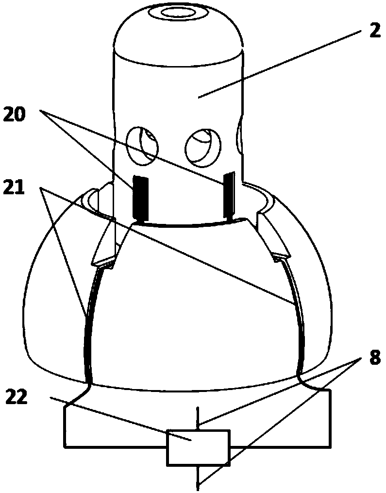
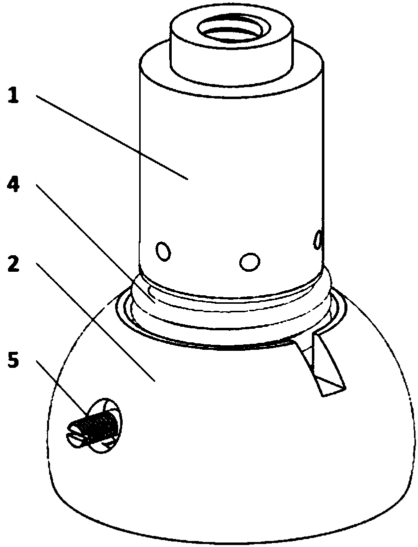
[0041] figure 1 An embodiment of the present invention is given, specifically, an electromagnetically driven two-stage compression release mechanism is used, and the electromagnet 18 is selected as a non-pyrotechnic driving element to drive the slider. Such as figure 1 As shown, the separation cap 1 is installed on the upper cage 2, and is limited by the upper ball 3, and the position of the upper ball 3 is jointly determined by the separation cap 1, the upper cage 2 and the release pin 10; The bottom of the upper ball 3 is set on the upper cage 2, and can slide up and down in the rectangular track on the upper cage 2; t...


PUM


Abstract

The invention provides a non-fire-worker-driven two-stage compressing releasing mechanism. Pretightening force applied to the mechanism can be accurately measured by means of strain gages; in the compressing state, a separating cap is limited by upper balls; a releasing pin is clamped by lower balls; the positions of the upper balls are determined by the separating cap, an upper retainer and the releasing pin; the positions of the lower balls are determined by the releasing pin, a sliding block and a lower retainer; and the sliding block is compressed by an anti-impact spring. During releasing, a non-fire-worker-driven element is powered on to start working to drive the sliding block to upwards move, after the sliding block upwards moves by a certain distance, the lower balls enter a groove of the sliding block, the releasing pin is unclamped and moves downwards under the effect of a driving spring, then the upper balls are unrestrained and fall into a groove of the releasing pin, theseparating cap is separated, and thus releasing is completed. In this mechanism, a plurality of spherical pairs are adopted, the influence of moment transferring on the part cooperation relationship and the releasing reliability is avoided, and meanwhile the mounting accuracy requirement is reduced; and control is convenient, vibration resistance is high, the borne load is large, and reliability is high.

Description

technical field [0001] The invention relates to the technical field of space release mechanisms, in particular to a non-pyrotechnic-driven compression release mechanism capable of bearing large loads. Background technique [0002] On spacecraft such as rockets, satellites, and spacecraft, there are multiple separation and release requirements, such as the deployment of solar panels, the separation of multi-stage launch vehicles or escape towers, etc., requiring devices that can maintain compression for a long time and controllable release . At present, more pyrotechnic connection and separation mechanisms are used. The work of this device is one-time. During the separation process, it will not only generate a large impact, but also generate explosive fragments and dust that will remain in the spacecraft. It will have adverse effects on system security and space environment. Especially for my country's next-generation high-precision spacecraft, such as the compression and r...

Claims


Application Information

Patent Timeline
Patent Type & Authority Applications(China)
IPC IPC(8): B64G1/64
CPCB64G1/645
Inventor 付佳丽谭帅
Owner 北京深空动力科技有限公司
Why Eureka
Try Eureka