

Descent-restricting device
a technology of restricting device and reducing device, which is applied in the direction of battery/fuel cell control arrangement, electric propulsion mounting, battery/cell control arrangement, etc., and can solve the problems of poor vehicle operation and user-friendliness
- Summary
- Abstract
- Description
- Claims
- Application Information
AI Technical Summary
Benefits of technology
Problems solved by technology
Method used
Image

Examples
first embodiment
[0021] A descent-restricting device according to the present invention is installed in an electric vehicle.
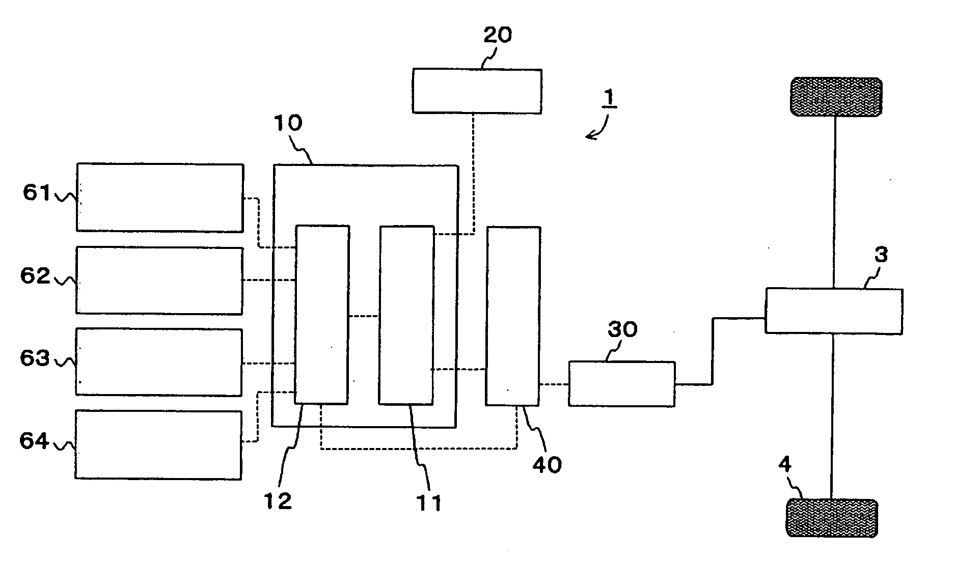
[0022] As shown in FIG. 1, a descent-restricting device 1 includes a motor control portion 10, a power source, 20, a motor 30, and a short-circuit switch portion 40, for restricting a moving-back of a vehicle (i.e., unwanted downward movement at slope) when the vehicle starts from a stationary state on an upward incline of a hill (i.e., both at forward movement and backward movement).
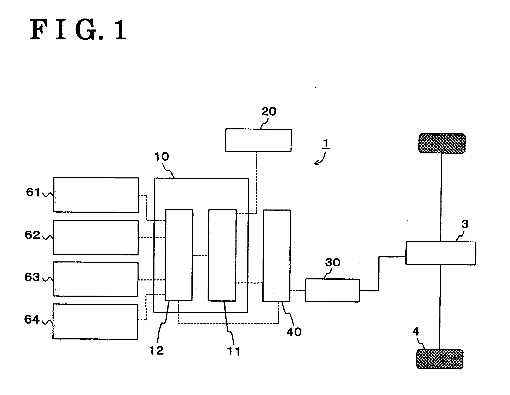
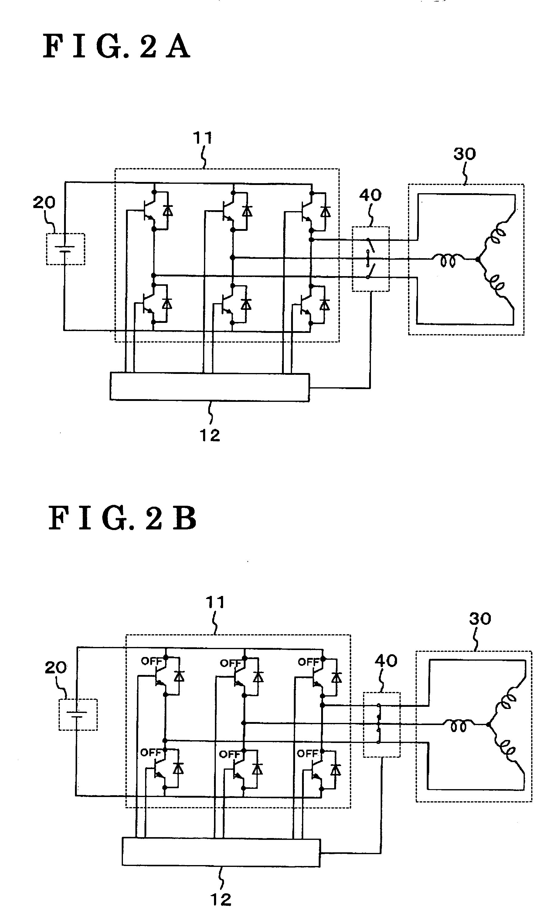
[0023] The motor control portion 10 (i.e., serving as a motor controller) includes an inverter 11 and a motor command portion 12, and is connected to the power source 20 for controlling power provided from the power source 20 to the motor 30.
[0024] The inverter 11 (i.e., serving as a power converter) converts direct electric voltage supplied from the power source 20 to three phase alternating voltage in accordance with torque command of the motor command portion 12, and outputs the converted thre...
second embodiment
[0037] Operation of the descent-restricting device 201 according to the present invention will be explained as follows. For the explanatory purpose, it is determined that a vehicle front is directed to upward incline of the hill.
[0038] First, when the manual operation portion 250 is turned ON at a stationary state of the vehicle, the short circuit switch potion 240 is short-circuited (i.e., Step B1). That is, by inputting the information regarding the ON state at the manual operation portion 250 into a motor command portion 212, the motor command portion 212 short-circuits the wirings by the short circuit switch portion 240, and controls so that all the circuit elements of an inverter 211 assume OFF. Thus, the descent-restricting state is established. Timing for turning ON the manual operation portion 250 may be either before or after moving the shift lever from N range to D range and either before or after depressing the brake pedal.
[0039] Second, the motor command portion 212 mai...
third embodiment
[0043] Operation of the descent-restricting device 301 according to the present invention will be explained as follows. For the explanatory purpose, it is determined that a vehicle front is directed to upward incline of the hill.
[0044] First, when a vehicle is at stationary state and the engine 302 is at an idling state, wirings are short-circuited at a short circuit switch portion 340 by depressing a brake pedal in order to prevent moving-back of the vehicle as a preparation for starting the vehicle from a stationary state on an upward incline of the hill, and by shifting a shift lever form N range to D range (i.e., Step C1). That is, a motor command portion 312 short-circuits the wirings at the short circuit switch portion 340, and controls all circuit elements of the inverter 311 to be OFF by detecting that the vehicle speed is at 0 km / h by a speed detection portion 361, inputting the information regarding the vehicle speed into the motor command portion 312, simultaneously, by d...
PUM
 Abstract
Description
Claims
Application Information