Rotating tub washer binary damper system

a technology of rotating tub washers and dampers, which is applied in the direction of shock absorbers, braking systems, transportation and packaging, etc., can solve the problems of not being particularly easy to manufacture and assemble, and complicating manufacture and assembly, so as to dampen the problematic movement

Inactive Publication Date: 2005-09-29
LORD CORP
View PDF10 Cites 27 Cited by
  • Summary
  • Abstract
  • Description
  • Claims
  • Application Information

AI Technical Summary

Benefits of technology

[0008] The invention includes a rotating tub washer. The washer includes a frame, a rotating tub, and a rotating tub washer on-off binary damper system for damping a problematic movement between the frame and the rotating tub. The on-off binary damper system includes a friction pad and a housing friction damper surface with the friction pad in contact with the housing friction damper surface. The on-off binary damper system includes an electromagnetic coil core and a magnetic locking slide, with the electromagnetic coil core disposed proximate the magnetic locking slide with a slide gap between the electromagnetic coil core and the magnetic locking slide to provide for relative sliding motion between the electromagnetic coil core and the magnetic locking slide, wherein a current supplied to the electromagnetic coil core removes the slide gap and electromagnetically locks the electromagnetic coil core and the magnetic locking slide together with the relative sliding motion transferred to the friction pad, with the friction pad rubbing against the housing friction damper surface inorder to dampen the problematic movement between the frame and the rotating tub.

Problems solved by technology

In particular, such dampers typically require a dynamic seal and a compliant containment member which are not particularly easy to manufacture and assemble.
Further, the fluid type dampers can have significant “off-state” forces which can further complicate manufacture and assembly.

Method used


Image

  • Rotating tub washer binary damper system
  • Rotating tub washer binary damper system
  • Rotating tub washer binary damper system

Examples


example

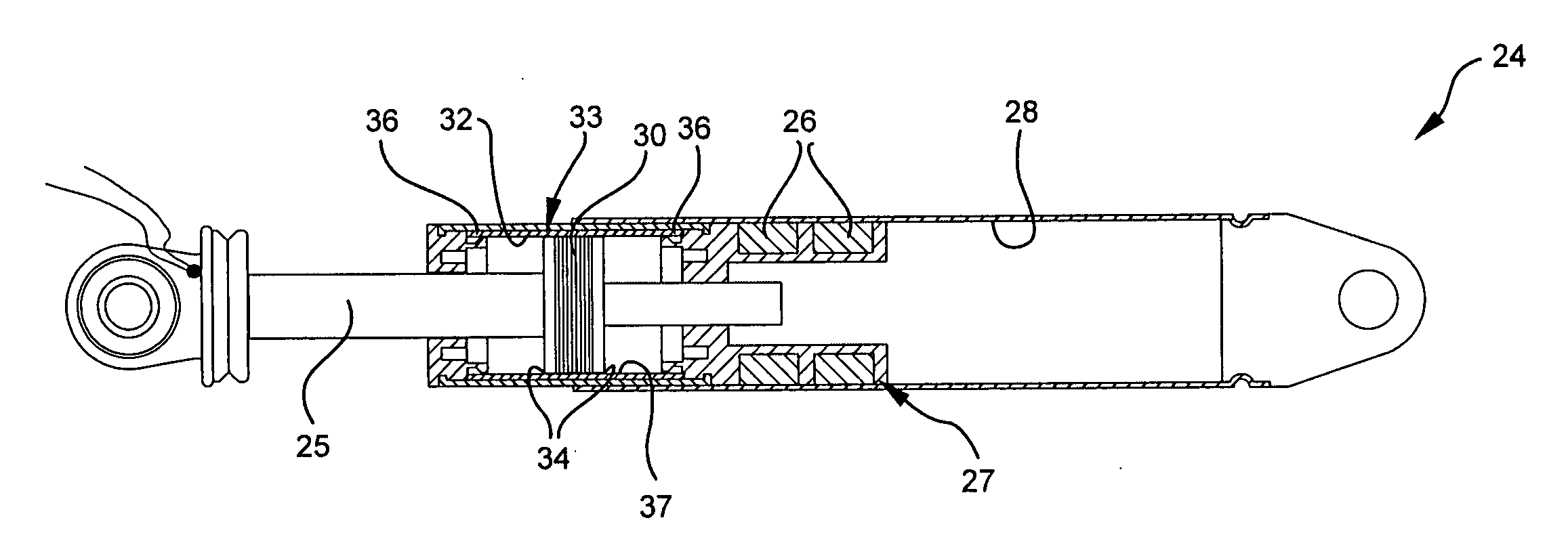
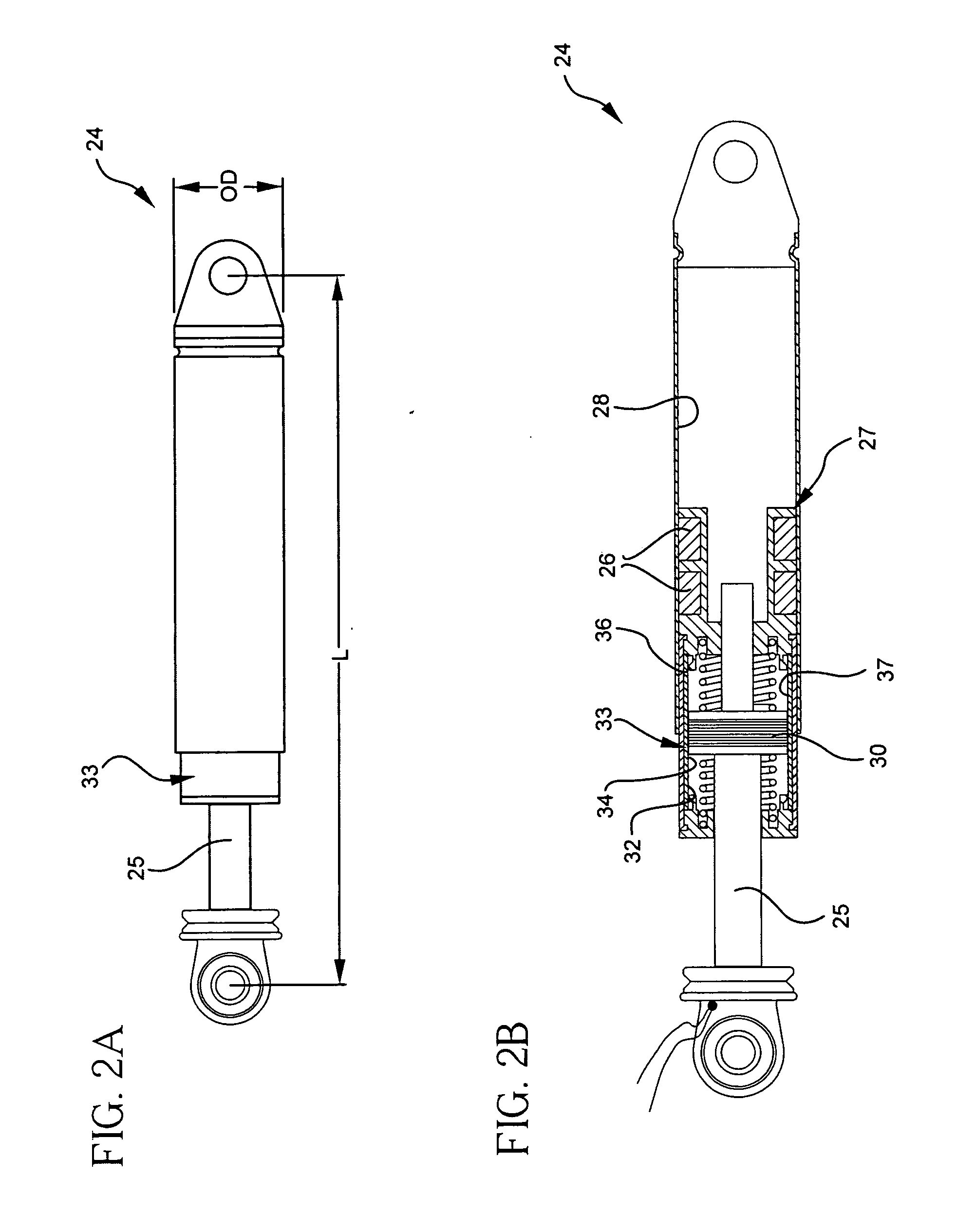
[0050] A damper system 24 as shown in FIG. 2C without the centering springs was made with the friction pad sponge rings 26 made from a high strength ether-based polyurethane foam that was a mixture of closed and open cells. The foam had a firmness rating of 8 and is rated at 65 PSI at 25% deflection in compression. It had a density of 30 pounds per cubic foot and a tensile strength of 705 PSI. The rings were formed from strips of foam 6.5 mm thick. The overall dimension of the damper 24 as shown in FIG. 2A had a damper length L between eye center ends of a max of 275 mm and min of 190 mm with the OD 32 mm. The polyurethane foam was lubricated with a synthetic plastic on steel lubricating grease (such as Kluber Lubrication (Polylub GLY 801). It is has a rating of NLGI 1 and uses a very high viscosity base oil (730 cSt at 40 C).

[0051] Electrical details of the electromagnetic coil core 30 were:

Coil winding:900turns of 34 AWG magnet wireCoil resistance:60ohmsMaximum current:0.3ampsM...


PUM


Abstract

The invention provides a rotating tub washer with an on-off binary damper system for damping a problematic movement between the washer frame and the rotating tub. The on-off binary damper system has a friction pad and a housing friction damper surface, with the friction pad in contact with said housing friction damper surface. The on-off binary damper system has an electromagnetic coil core and a magnetic locking slide with a slide gap between said electromagnetic coil core and said magnetic locking slide to provide for relative sliding motion between the electromagnetic coil core and the magnetic locking slide, wherein a current supplied to said electromagnetic coil core removes the slide gap and electromagnetically locks the electromagnetic coil core and the magnetic locking slide together with the relative sliding motion transferred to the friction pad, with the friction pad rubbing against said housing friction damper surface inorder to dampen the problematic movement between the frame and the rotating tub.

Description

[0001] This application claims the benefit of, and incorporates by reference, U.S. Provisional Patent Application No. 60 / 637,898 filed on Dec. 21, 2004. This application claims the benefit of, and incorporates by reference, U.S. Provisional Patent Application No. 60 / 556,257 filed on Mar. 25, 2004.FIELD OF THE INVENTION [0002] The present invention relates to rotating tub washers and magnetically actuated motion control devices. In particular the present invention relates to rotating tub washers with magnetically actuated binary damper systems to control motion. BACKGROUND OF THE INVENTION [0003] Magnetically actuated motion control devices such as magnetically controlled dampers or struts provide motion control, e.g., damping that is controlled by the magnitude of an applied magnetic field. Much of the work in the area of magnetically controlled dampers has focused on either electrorheological (ER) or magnetorheological (MR) dampers. The principle underlying both of these types of d...

Claims


Application Information

Patent Timeline
Patent Type & Authority Applications(United States)
IPC IPC(8): B60T1/00D06F37/20D06F37/22F16F7/08F16F7/09F16F15/02F16F15/03
CPCD06F37/20D06F37/22F16F15/03F16F7/09F16F7/082
Inventor CARLSON, J. DAVID
Owner LORD CORP
Why Eureka
Try Eureka