
Pipes having wedging circumferential grooves

Inactive Publication Date: 2005-09-29
VICTAULIC
View PDF18 Cites 31 Cited by
  • Summary
  • Abstract
  • Description
  • Claims
  • Application Information

AI Technical Summary

Benefits of technology

[0056] Pipes and pipe couplings according to the invention incorporate the advantages of a rigid connection with a reliable visual indicator for confirming that the coupling properly engages the pipes to effect a fluid tight joint. The couplings have tolerances allowing them to be economically produced and still yield a substantially rigid joint between pipes.

Problems solved by technology

Many couplings according to the prior art do not reliably provide the desired degree of rigidity mainly because they use keys having rectangular cross-sections that are narrower than the width of the grooves that they engage.
This condition may result in inconsistent contact between the coupling and the pipes which allows too much free play and relative movement, for example, axially, rotationally or angularly, between the pipes.
It is also difficult to ensure that such keys properly engage the grooves.
Couplings which provide a more rigid connection may be ineffective to force the pipe ends apart at a desired distance from one another so that the keys and grooves are in proper alignment and the pipes are properly spaced.
The movement of the pipes, although small, is effected as the couplings are engaged with each other and the pipe and may required that significant torque be exerted upon the fasteners used to clamp the coupling to the pipes.
For such couplings, it is also difficult to reliably visibly ensure that the couplings have been properly installed so that the keys engage the grooves and the pipes are spaced apart as required to ensure a fluid tight seal.

Method used


Image

  • Pipes having wedging circumferential grooves
  • Pipes having wedging circumferential grooves
  • Pipes having wedging circumferential grooves

Examples


Embodiment Construction

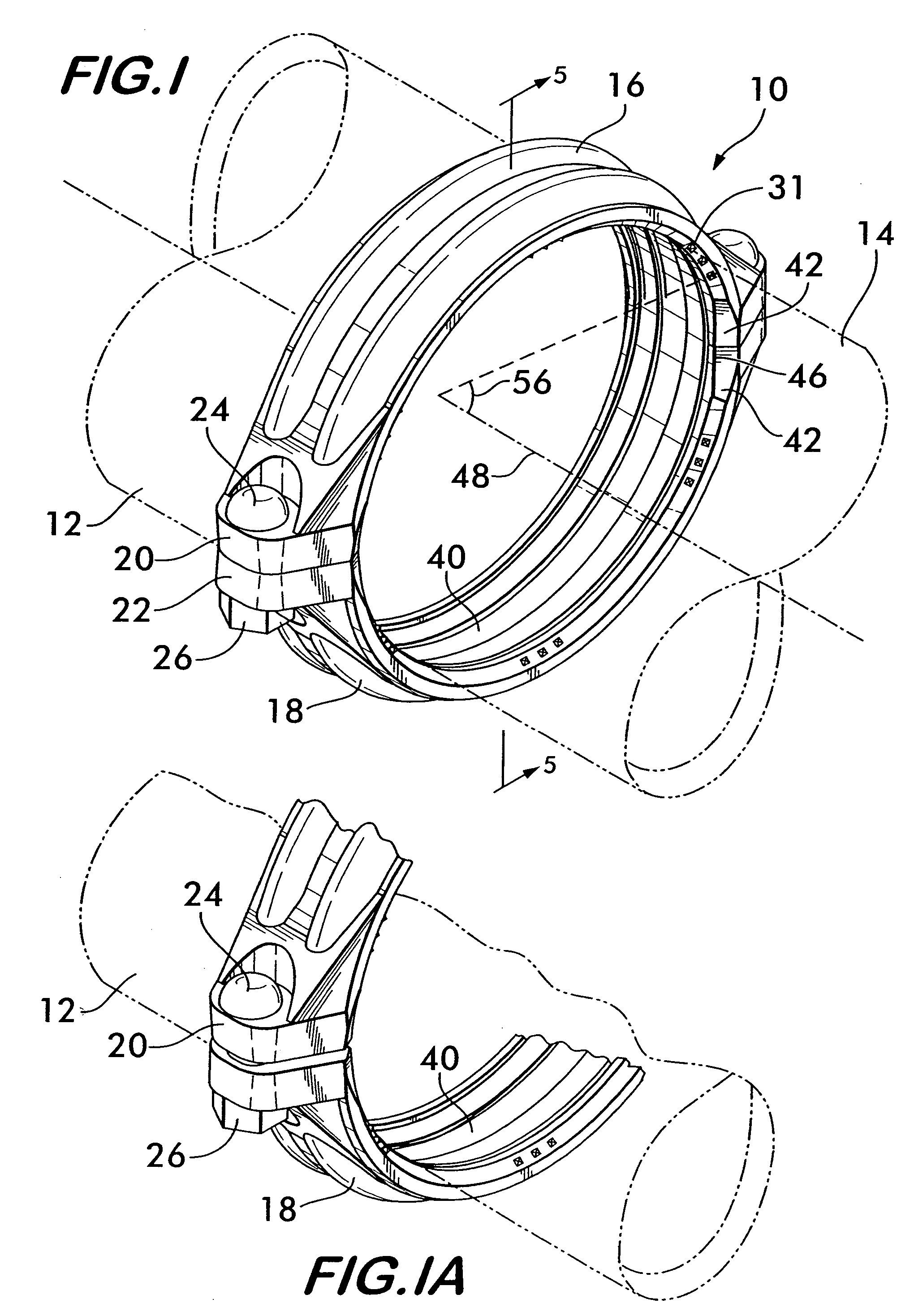
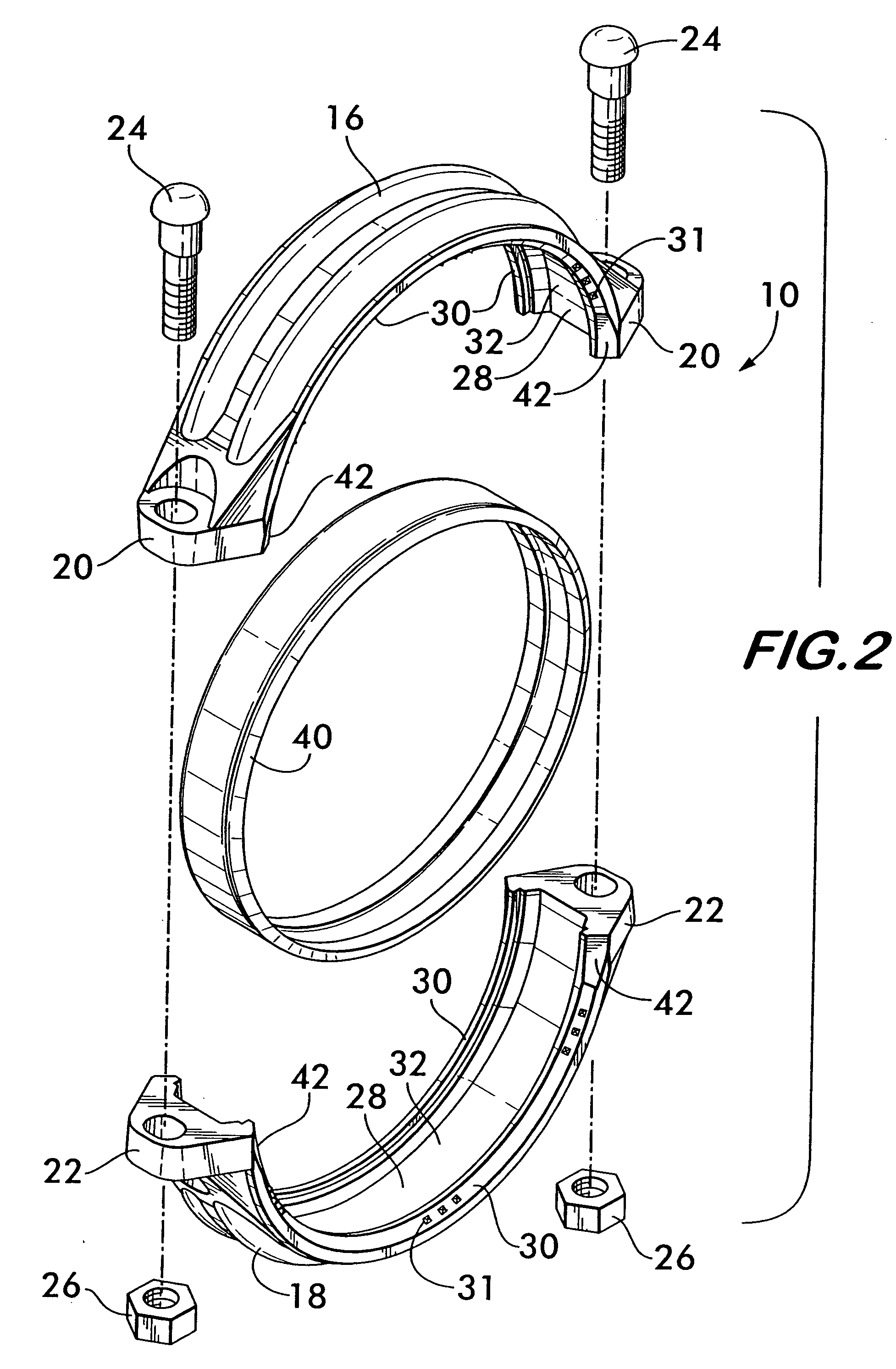
[0026]FIG. 1 shows a pipe coupling 10 for connecting two pipes 12 and 14 co-axially end to end. As shown in FIG. 2, coupling 10 is comprised of at least two segments 16 and 18. Each segment 16 and 18 has lugs 20 and 22 respectively, the lugs being positioned at or proximate to each end of the segments. The lugs 20 at each end of segment 16 align with the lugs 22 at each end of segment 18. Lugs 20 and 22 are adapted to receive fasteners, preferably in the form of bolts 24 and nuts 26 for joining the segments to one another end to end surrounding the pipes 12 and 14. In one embodiment, shown in FIG. 1, the lugs 20 engage the lugs 22 in what is known as “pad-to-pad engagement” with the lugs contacting one another when the segments 16 and 18 are properly engaged with the pipes 12 and 14 as explained below. The lugs may also be attached to each other in spaced apart relation when the segments 16 and 18 are properly engaged with the pipes 12 and 14, as illustrated in FIG. 1A.

[0027] Altho...


PUM

PropertyMeasurementUnit
Angleaaaaaaaaaa
Shapeaaaaaaaaaa
Widthaaaaaaaaaa

Abstract

Pipes and fittings having circumferential grooves proximate to their ends are disclosed. The grooves are formed of first and second side surfaces positioned in spaced apart relation to one another. A floor surface extends between the first and second side surfaces. The first side surface is positioned proximate to the end of the pipe and is oriented perpendicularly to the floor surface. The second side surface is formed of first and second surface portions. The second surface portion is positioned adjacent to the floor surface, and is oriented perpendicularly to it. The first surface portion is oriented at an angle to the floor surface. The second side surface may also have either a convex or a concave shape. Wedging action between the groove and a coupling is facilitated by having the width of each groove being greater at the surface of the pipe than it is at the floor surface.

Description

FIELD OF THE INVENTION [0001] The invention concerns pipes having circumferential grooves and couplings for joining the pipes end to end and effecting a substantially rigid or flexible fluid tight joint therebetween. BACKGROUND OF THE INVENTION [0002] Couplings for joining pipes together end to end comprise arcuate segments that circumferentially surround co-axially aligned pipes and engage circumferential grooves positioned proximate to the ends of each pipe. The couplings are also used to connect pipes to fluid control components such as valves, reducers, strainers, restrictors, pressure regulators, as well as components to components. Although in the description which follows pipes are described, they are used by way of example only, the invention herein not being limited for use only with pipes per se. It should also be noted that the term “pipe” as used herein refers to straight pipes as well as elbows, tees and other types of fittings. [0003] The segments comprising the coupli...

Claims


Application Information

Patent Timeline
IPC IPC(8): B21D17/04F16L17/00F16L17/025F16L21/06F16L23/08F16L23/16F16L35/00F16L43/00
CPCB21D17/04F16L17/025F16L17/04F16L21/065Y10T29/49948F16L23/22F16L25/12F16L43/00F16L23/08F16L21/06F16L21/02
Inventor DOLE, DOUGLAS R.
Owner VICTAULIC
Features
  • Generate Ideas
  • Intellectual Property
  • Life Sciences
  • Materials
  • Tech Scout
  • Unparalleled Data Quality
  • Higher Quality Content
  • 60% Fewer Hallucinations
Learn More