System and method for selectively reading RFID devices

a selective reading and radio frequency identification technology, applied in the field of antenna arrangement for a radio frequency identification (rfid) system, can solve the problems of relatively limited read range of passive transponders, relatively limited interrogation zone,

Active Publication Date: 2005-09-29
AVERY DENNISON CORP
View PDF28 Cites 101 Cited by
  • Summary
  • Abstract
  • Description
  • Claims
  • Application Information

AI Technical Summary

Benefits of technology

[0007] According to another aspect of the invention, an RFID detection system includes an RFID device reader and jamming signal transm...

Problems solved by technology

One traditional drawback of RFID systems which include passive transponders has been their relatively limited read range (i.e., relatively limited interrogation zone).
In the case of detection of RFID tagged packages on a conveyor, improvements in reading distance o...

Method used


Image

  • System and method for selectively reading RFID devices
  • System and method for selectively reading RFID devices
  • System and method for selectively reading RFID devices

Examples


Embodiment Construction

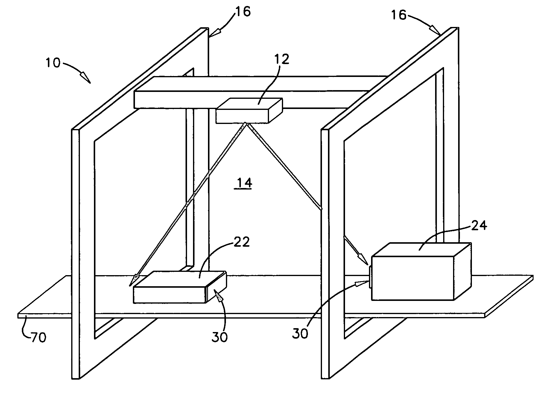
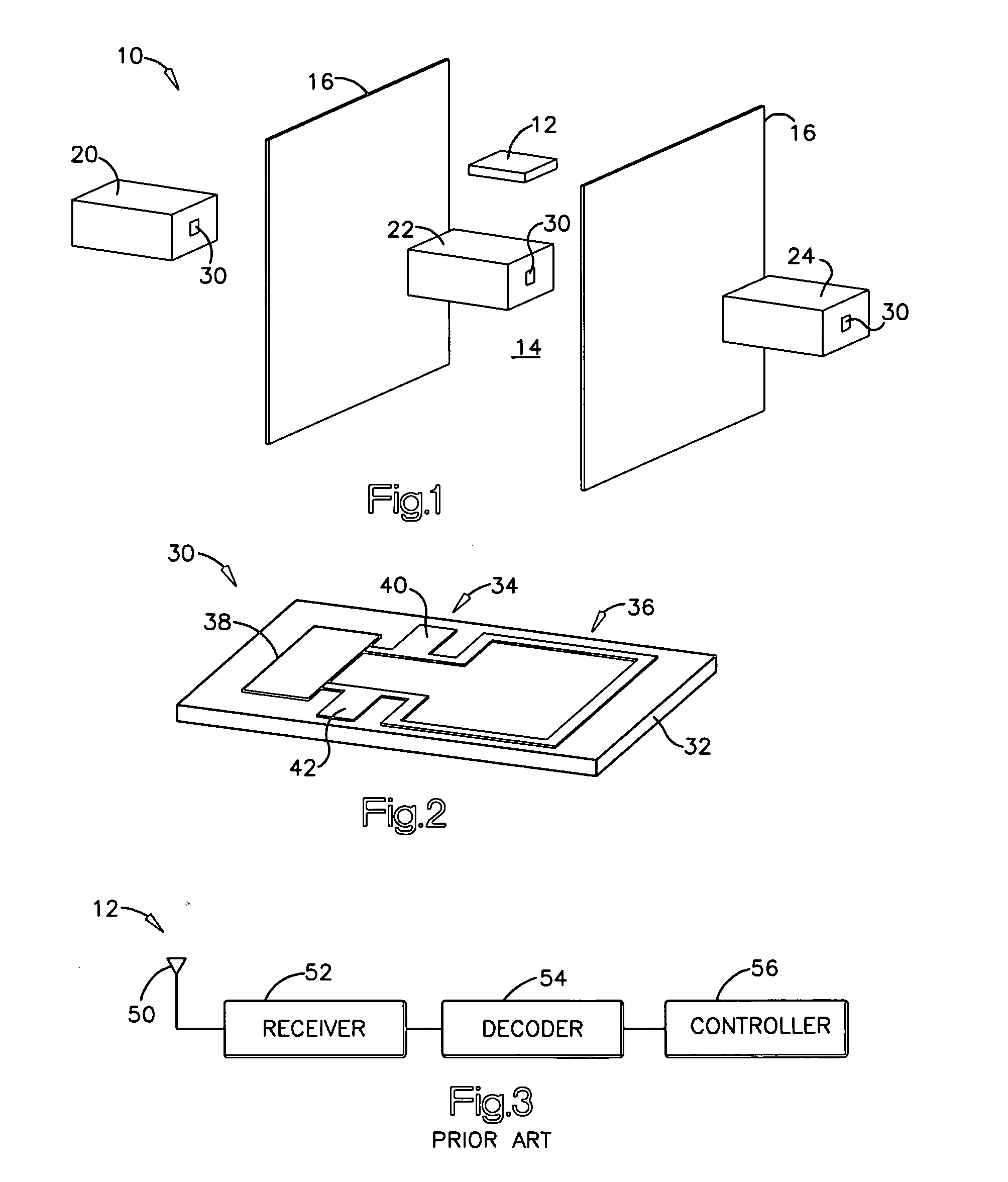
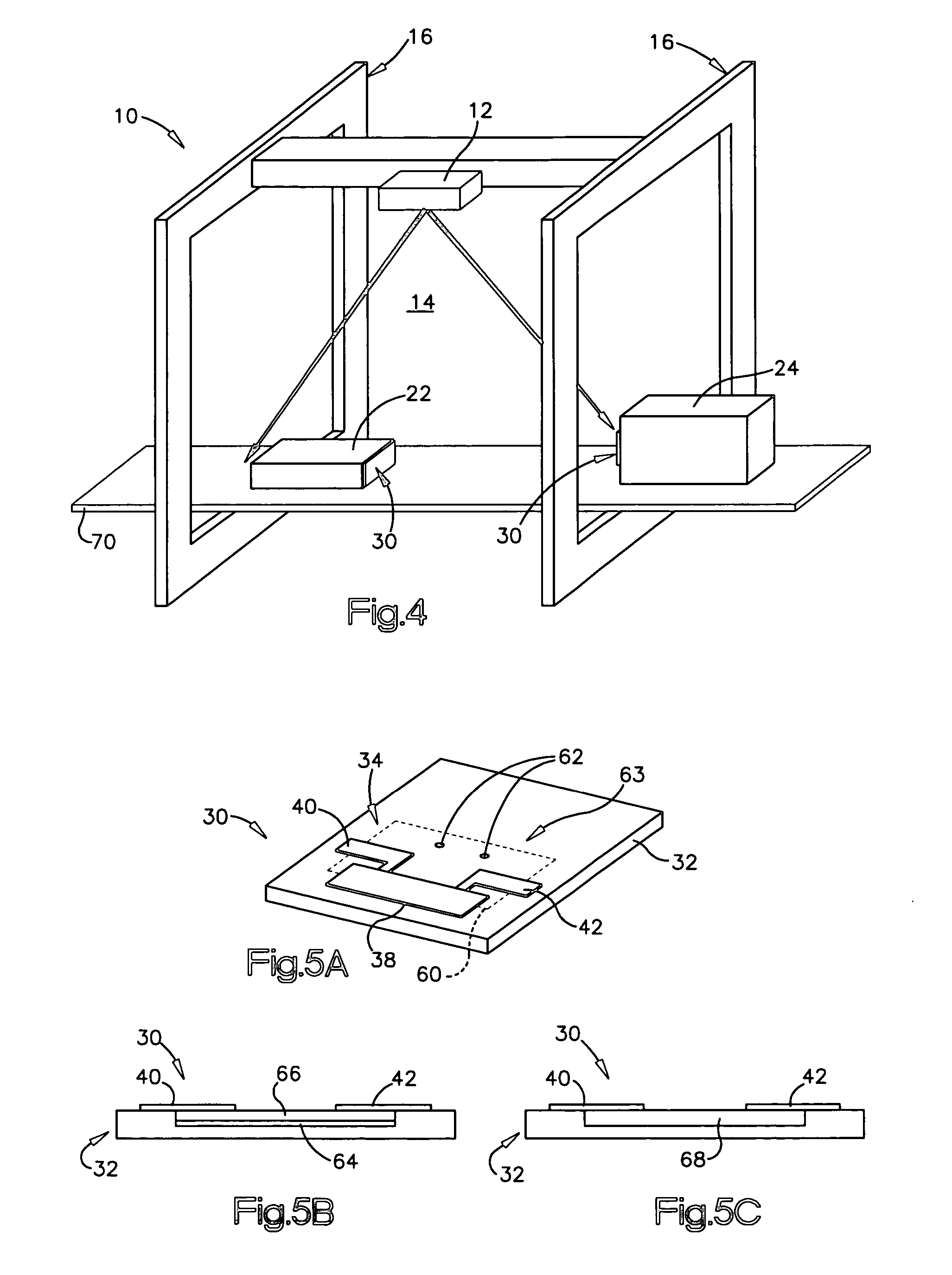
[0034] A radio frequency identification (RFID) device detection system includes an RFID device reader configured to detect RFID devices within a predetermined designated area, and a jamming system that includes two or more jamming signal transmitters configured to prevent the RFID device reader from detecting and reading devices outside of the designated area. The RFID device reader uses a communication signal to interact with RFID devices within the predetermined area. The jamming signal transmitters transmit a jamming signal to prevent interaction between the RFID device reader and RFID devices outside of the predetermined area. The jamming signal transmitters may include a pair of low-frequency field generator loops driven out of phase with one another. Additional jamming signal transmitters may be placed around the designated area, in order to jam RFID devices outside the designated area, in any of a variety of possible locations and orientations. RFID devices for use with the d...


PUM


Abstract

A radio frequency identification (RFID) device detection system includes an RFID device reader configured to detect RFID devices within a predetermined designated area, and two or more jamming signal transmitters configured to prevent the RFID device reader from detecting and reading devices outside of the designated area. The jamming signal transmitters may include a pair of low-frequency field generator loops driven out of phase with one another. RFID devices for use with the detection system may have a pair of antennas, one for detection by the RFID reading system, and another antenna for use in receiving signals from the jamming signal transmitters, in order to prevent communication with a wireless communication device such as an RFID chip, to which the antennas are coupled. The two antennas may be coupled to the RFID chip in parallel, with the antennas each coupled to the same contacts of the RFID chip.

Description

TECHNICAL FIELD OF THE INVENTION [0001] The present invention relates to an antenna arrangement for a radio frequency identification (RFID) system for use in tracking packages and other articles in specified areas, such as on a portion of a conveyor belt. In addition, the present invention relates to a system for detecting RFID devices in specified areas. More specifically, the present invention relates to an RF reader array in combination with other devices that allow discrimination of multiple articles in the vicinity of the specified area. DESCRIPTION OF THE RELATED ART [0002] The use of a radio frequency identification (RFID) system to identify and monitor objects is well known in the art. In such a system RFID labels or tags, referred to collectively as “RFID devices”, are attached or otherwise coupled to objects to be tracked or otherwise monitored. A conventional RFID device may utilize a gated antenna array that includes a pair of vertically mounted antennas. The vertically ...

Claims


Application Information

Patent Timeline
IPC IPC(8): G06K7/00G06K7/08G06K19/07
CPCG06K7/0008H04K3/28G06K7/10336G06K7/10435G06K19/0723H04K3/43H04K3/60H04K3/825H04K3/86H04K2203/12H04K2203/14H04K2203/20H04K2203/32H04K2203/34G06K7/10079H04K3/84H04K3/94G06K19/077G06K17/00G06K7/00
Inventor FORSTER, IAN J.
Owner AVERY DENNISON CORP
Why Eureka
Try Eureka