Obstacle detecting system and method

a technology for detecting systems and obstacles, applied in the field of obstacles detecting systems and methods for vehicles, can solve the problems of difficult application of techniques to curved roads, difficult classification of obstacles, and sensitive variation in recognition of obstacles, so as to effectively detect or prevent collision risk or traffic lane deviation risk, and quickly and effectively determine obstacles

Inactive Publication Date: 2012-04-05
ELECTRONICS & TELECOMM RES INST +1
View PDF7 Cites 60 Cited by
  • Summary
  • Abstract
  • Description
  • Claims
  • Application Information

AI Technical Summary

Benefits of technology

[0011]The present invention is directed to quickly and effectively determine an obstacle present in a forward target distance of a moving means, by obtaining 3-D image information based on image information on a projection shape of a laser beam and obtaining 2-D image information on actual surroundings to identify movement of the obstacle and effectively detect or prevent collision risk or traffic lane deviation risk.

Problems solved by technology

Accordingly, there is a problem in that the shape of the detected object is not identified, and it is not easy to classify the obstacles.
However, because of the linearity of the laser, it is difficult to apply the technique to a curved road.
The method using the stereo cameras utilizes images from two 2-D cameras, but substantially includes the problems associated with the forward monitoring technology using the camera image according to the related art.
That is, since the obstacle is recognized on the screen including a background in the process of recognizing the pattern based on the image obtained from the cameras, there is a problem in that the recognition of the obstacle is sensitively varied depending upon day and night or illumination variation.
However, there is a problem in that, if the signal process is executed in real time and then is used to control the collision protection of the driving vehicle, a high-performance computing performance is required.
In addition, a technique of recognizing the image information pattern should be added so as to recognize the obstacle and thus to prevent the collision on the basis of the 3-D image information obtained from the means, but it is not easy to obtain the distance information between the vehicle and the front vehicle or leftward or rightward moving information at the same time.
That is, the above-described technology is not sufficient for the means for quickly and accurately controlling the signal processing.

Method used


Image

  • Obstacle detecting system and method
  • Obstacle detecting system and method
  • Obstacle detecting system and method

Examples


examples

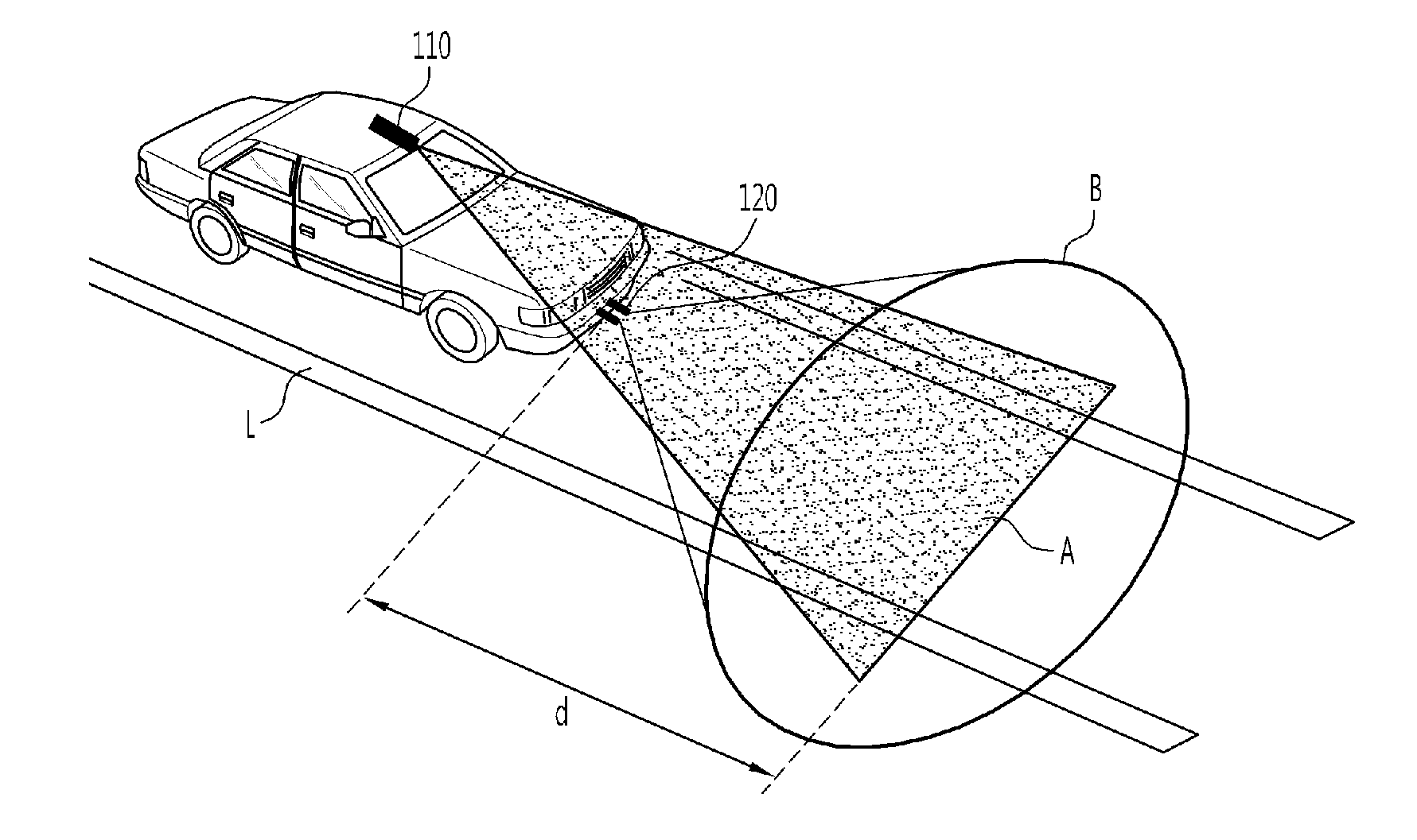
[0078]FIG. 3 is a diagram illustrating one example of the obstacle detecting system 100 according to one embodiment of the present invention which is applied to a vehicle.

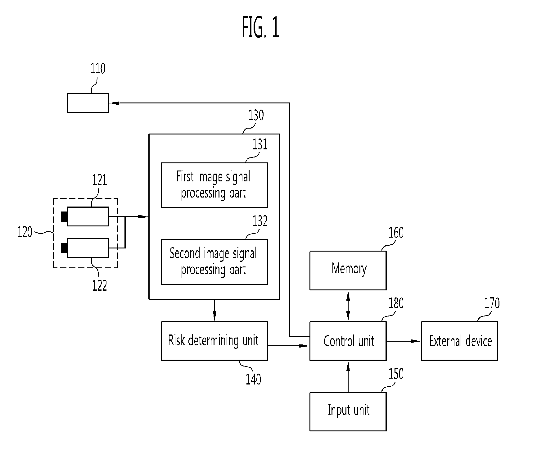
[0079]As shown in FIG. 3, the vehicle driving on the road surface with a traffic lane 310 is provided with the laser beam scanning unit 110 at the upper end thereof, and the image information acquiring unit 120 at a relatively lower position (e.g., a lower portion of the bumper formed at the front surface of the vehicle). The laser beam emitted from the laser beam scanning unit 110 can be scanned at a slope on the road surface in front of the vehicle. The first image acquiring part 121 of the image information acquiring unit 120 is installed to capture the whole range B including the region A on which the laser beam is projected.

[0080]If the distance d from the point to which the laser beam reaches to the front line of the vehicle is known, it is possible to determine the distance between the obstacle and the vehic...


PUM


Abstract

The obstacle detecting system includes a first image acquiring unit which acquires first image information by selectively receiving a laser beam emitted from at least one laser source toward a road surface at a target distance; a second image acquiring unit which acquires an image of actual surroundings as second image information; an image recognizing unit which recognizes an image of an obstacle by performing 3-D image recognition signal processing on line information of the laser beam using the first image information, and recognizes a pattern of the obstacle by performing pattern recognition signal processing on the second image information; and a risk determining unit which determines a possibility of collision due to presence of the obstacle within the target distance by classifying the recognized obstacles according to whether or not the image-recognized obstacle is matched with the pattern-recognized obstacle.

Description

CROSS-REFERENCE TO RELATED APPLICATION[0001]This application claims priority to and the benefit of Korean Patent Application No. 10-2010-0095838, filed Oct. 1, 2010, the disclosure of which is incorporated herein by reference in its entirety.BACKGROUND[0002]1. Field of the Invention[0003]The present invention relates to an obstacle detecting system and method for use in vehicles. More specifically, the present invention relates to a system and method for detecting an obstacle on a road, which can detect the obstacle existing within a forward safety distance of a driving vehicle to determine risk level on the basis of image information about a projection image of a laser beam directed toward a road surface and image information about the actual surroundings.[0004]2. Discussion of Related Art[0005]Recently, with the development of image forming apparatuses such as cameras, an interest in information processing techniques using images has gradually increased. In particular, in the auto...

Claims


Application Information

Patent Timeline
Patent Type & Authority Applications(United States)
IPC IPC(8): H04N7/18G06K9/00
CPCG06K9/00805H04N7/181G06V20/58
Inventor SUK, JUNG HEELYUH, CHUN GICHUN, IK JAECHUNG, WOOK JINLEE, JEONG HWANSHIM, JAE CHANGROH, TAE MOON
Owner ELECTRONICS & TELECOMM RES INST
Why Eureka
Try Eureka