Full-color flexible light source device

a light source device and full-color technology, applied in the field of full-color flexible light source devices, can solve the problems of uneven illumination of characters and/or marks of billboards, difficult to achieve optimal spacing, etc., and achieve the effect of quick assembly

Active Publication Date: 2005-09-29
HAYASHIBARA BIOCHEMICAL LAB INC
View PDF9 Cites 90 Cited by
  • Summary
  • Abstract
  • Description
  • Claims
  • Application Information

AI Technical Summary

Benefits of technology

[0006] It is an object of the present invention to provide a full-color flexible light source device in which each of a plurality of light source units thereof comprises a blue bare chip, a red bare chip having brightness three times of that of the blue bare chip, and a green bare chip having brightness six times of that of the blue bare chip, the bare chip is implemented as a C.O.B. (chip on board) type, and the R, G, and B bare chips are arranged in the shape of a triangle prior to being encapsulated as a C.O.B. type RGB LED. The light source device has advantages of being compact, capable of emitting a uniform light, and capable of being assembled quickly.
[0007] It is another object of the present invention to provide a full-color flexible light source device in which the C.O.B. type RGB light source units (e.g., LEDs) are coupled in series, and the light source units are in turn encapsulated by a flexible inner fixing member and a flexible outer fixing member so as to form a light source strip having an increased tensile strength and flexibility.

Problems solved by technology

A number of drawbacks have been found when the above light source strip is modified to become a full-color light source strip.
Such arrangement (i.e., optimum spacing) is difficult of achieving.
It is often that an uneven illumination is occurred on the characters and / or marks of a billboard.
This is not desirable.
Also, the circuitry of the former is complicated, resulting in an increase in the manufacturing cost.
Further, heat dissipation of LED is poor.
As a result, LEDs tend to malfunction.
Moreover, the size thereof is quite large and spacing between any two LEDs is also relatively large.
All of the above are not desirable.

Method used


Image

  • Full-color flexible light source device
  • Full-color flexible light source device
  • Full-color flexible light source device

Examples


Embodiment Construction

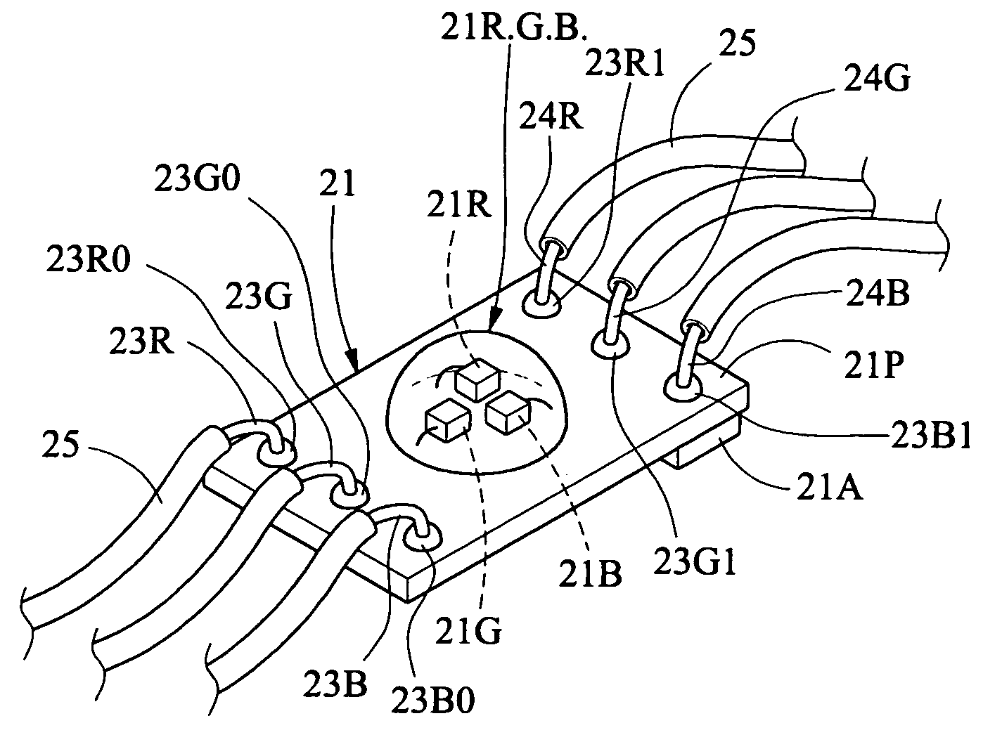
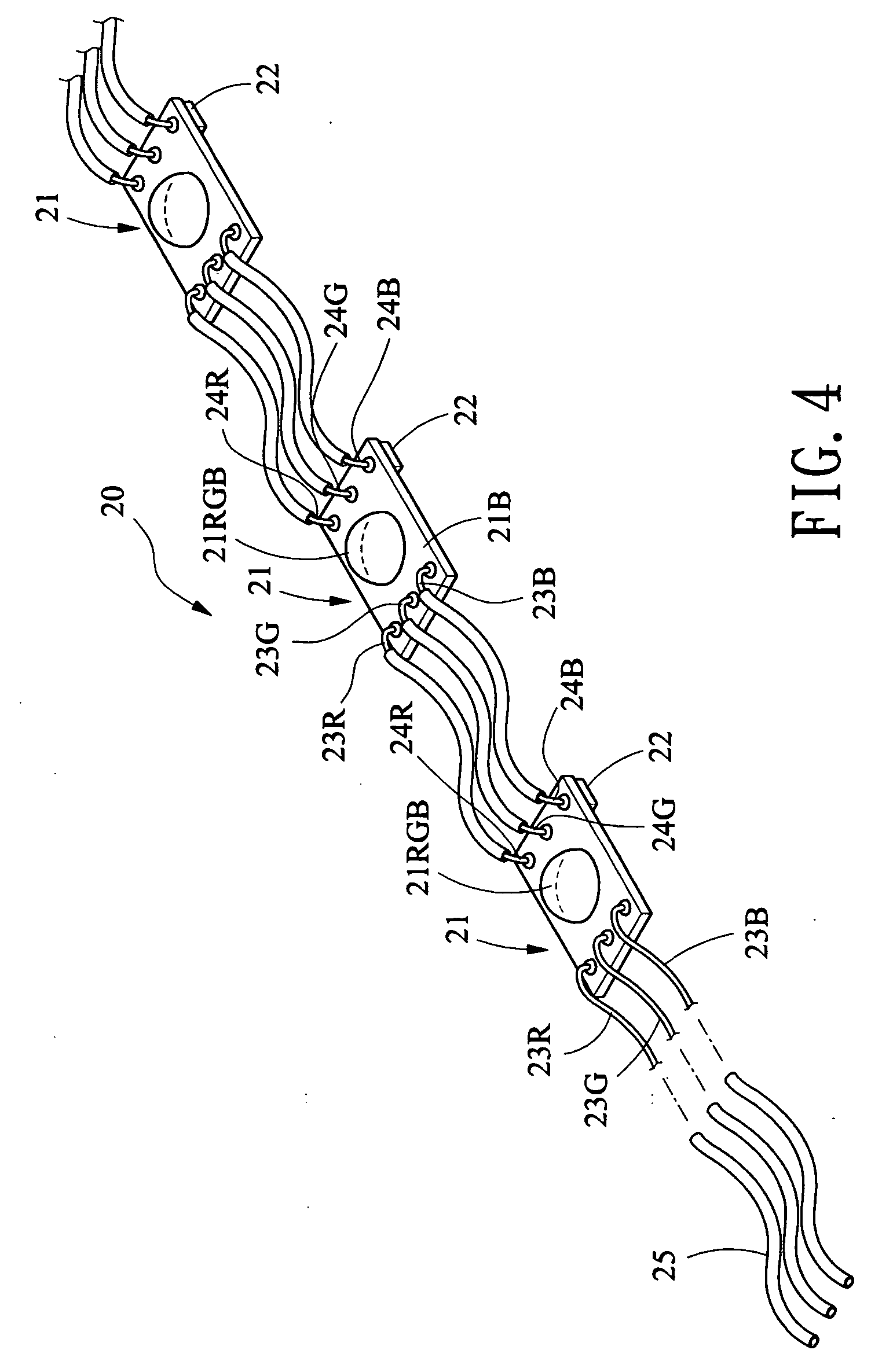
[0023] Referring to FIGS. 1 to 6, there is shown a light source device 20 constructed in accordance with a first preferred embodiment of the invention. The device 20 comprises a plurality of light source units 21 in which a first group of wires 23R, 23G, and 23B at one side of one light source unit 21 are electrically coupled to a second group of wires 24R, 24G, and 24B at the other side of an adjacent light source unit 21. This forms a serially coupled light source device including a plurality of C.O.B. (chip on board) type RGB light source units 21 (e.g., LEDs). The light source unit 21 comprises a circuit board 21P, a C.O.B. type LED 21R.G.B. Fixedly formed on the circuit board 21P, a first group of wires 23R, 23G, and 23B formed at one side, and a second group of wires 24R, 24G, and 24B formed at the other side.

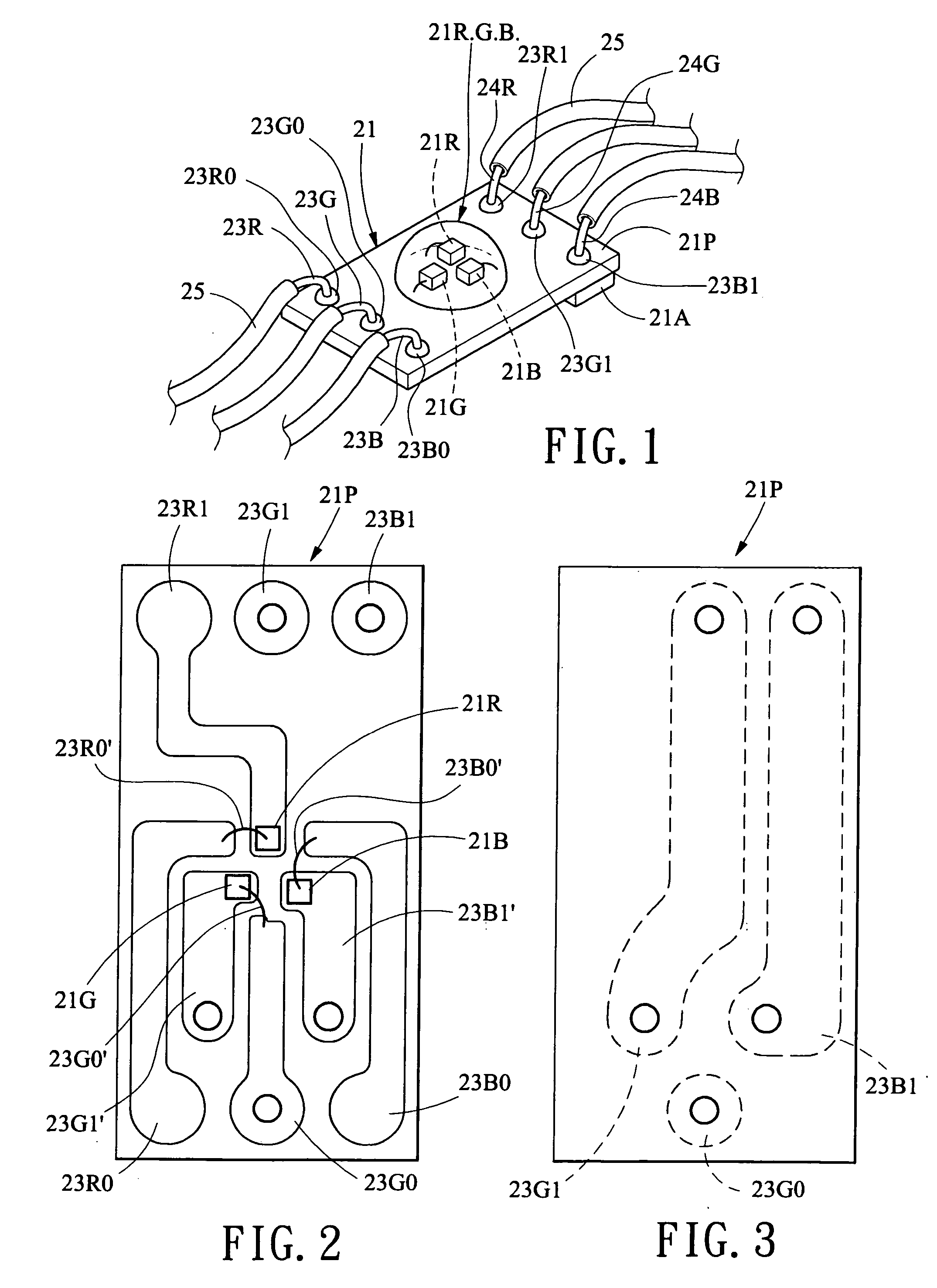
[0024] In FIGS. 2 and 3, the circuit board 21P is a board having both surfaces formed with printed circuits. The wire 23R is coupled to one end of a first circuit 23R0 o...


PUM


Abstract

A full-color flexible light source device is disclosed. The device includes a plurality of light source units each comprises a red LED, a green LED, and a blue LED arranged in the shape of a triangle. Each of the R, G, and B LEDs is a bare chip and the R, G, and B LEDs are encapsulated as a C.O.B. type RGB light source unit. The device is able to emit a uniform light. Also, the device has an increased tensile strength and flexibility as well as has waterproof and vibration-proof features. In other embodiments, the device is encapsulated by elongated, flexible, parallelepiped inner and outer fixing members or formed on a strip.

Description

BACKGROUND OF THE INVENTION [0001] 1. Field of The Invention [0002] The present invention relates to light source units and more particularly to a full-color flexible light source device comprising chip on board type red, green, and blue light source units (e.g., LEDs). [0003] 2. Description of Related Art [0004] A conventional light source strip comprises a plurality of LEDs (light-emitting diodes) serially coupled together in which each LED has a coupled resistor and can emit light of single color. A number of drawbacks have been found when the above light source strip is modified to become a full-color light source strip. This is because brightness difference between any two of R (red), G (green), and B (blue) LEDs is quite large. For example, brightness of three R LEDs is equal to that of one B LED. Brightness of six G LEDs is equal to that of one B LED. For obtaining a uniform brightness of the light source strip, a unit thereof is required to consist of three R LEDs, six G LED...

Claims


Application Information

Patent Timeline
Patent Type & Authority Applications(United States)
IPC IPC(8): F21S4/00F21V9/00H01L25/075H05B44/00
CPCF21S4/006F21S4/007F21Y2101/02Y10S362/80H05B33/0803H05B33/0821H05B33/0857F21Y2113/007H01L2224/48091H01L2224/4903H01L2224/49107F21S4/24F21S4/26F21Y2115/10F21Y2113/17H01L2924/00011H05B45/40H05B45/20H05B45/00H01L2924/00014H01L2924/01005
Inventor LIN, YUAN
Owner HAYASHIBARA BIOCHEMICAL LAB INC
Why Eureka
Try Eureka