Router and sip server

a protocol and server technology, applied in the field of routing and session initiation protocol (sip) servers, can solve the problems of inability to ensure the qos of users, the ip network is not ready for communication with near-real-time characteristics, and the user's qos cannot be guaranteed

Inactive Publication Date: 2005-09-29
HITACHI LTD
View PDF2 Cites 74 Cited by
  • Summary
  • Abstract
  • Description
  • Claims
  • Application Information

AI Technical Summary

Benefits of technology

[0033] The present invention can provide a network system, a SIP server, and a router which can provide an unchanged QoS service to the user even if the user terminal is moved. The present invention enables a QoS service specified for the user to be provided even when the user uses a non-registered terminal. With the present invention, a QoS servi

Problems solved by technology

The IP network is originally configured by a best-effort network and may not be ready for communication with near-real-time characteristics.
If the boundary node router serving the user terminal is changed because of the movement of the user terminal to another site, the addition of a new boundary node router, a change in the network configuration, and other reasons, t

Method used


Image

  • Router and sip server
  • Router and sip server
  • Router and sip server

Examples


first embodiment

1. First Embodiment

[0055] (Apparatus Configuration)

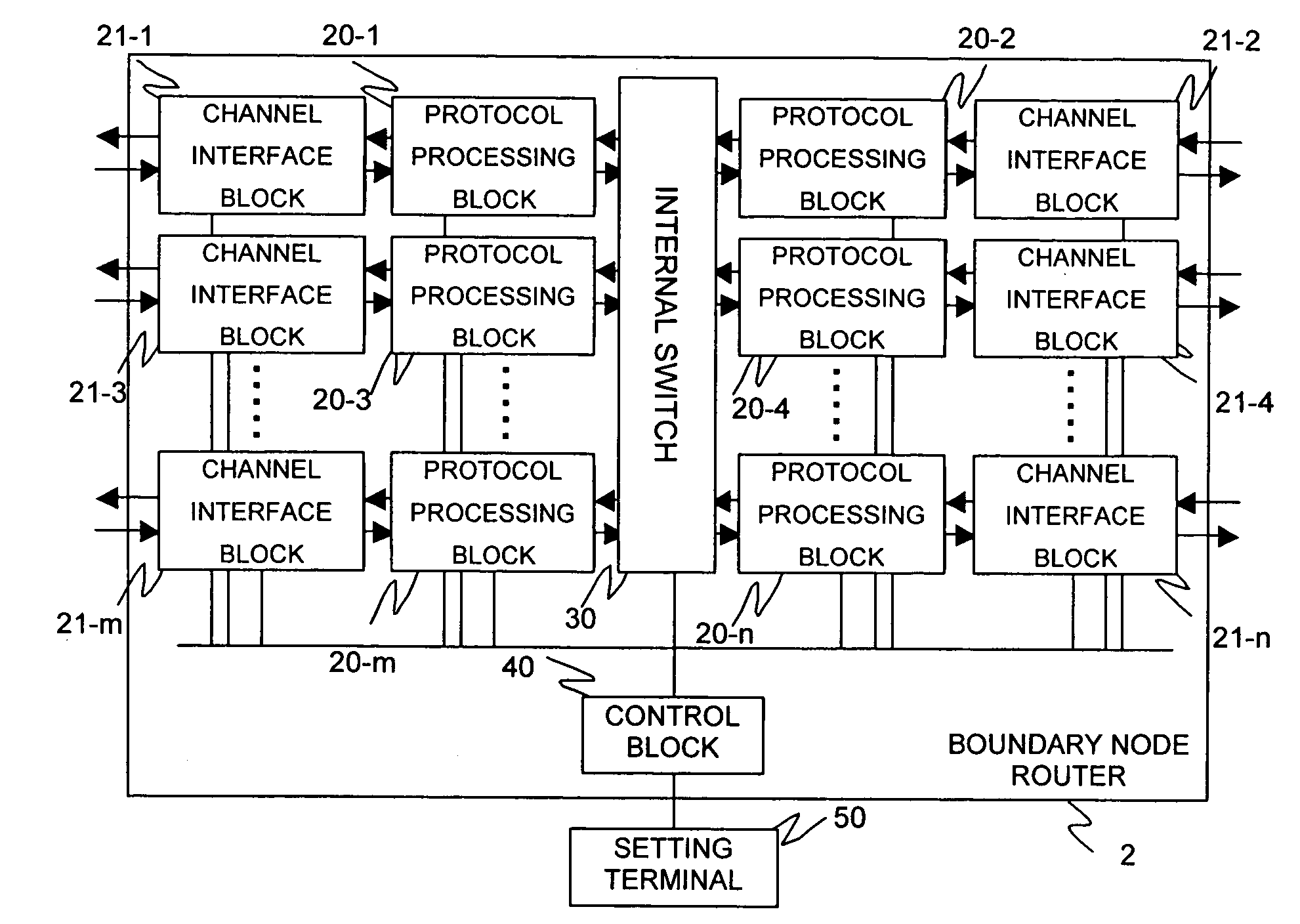
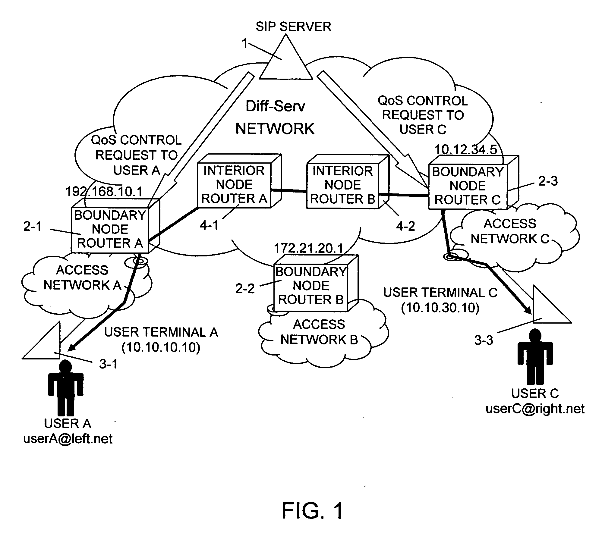
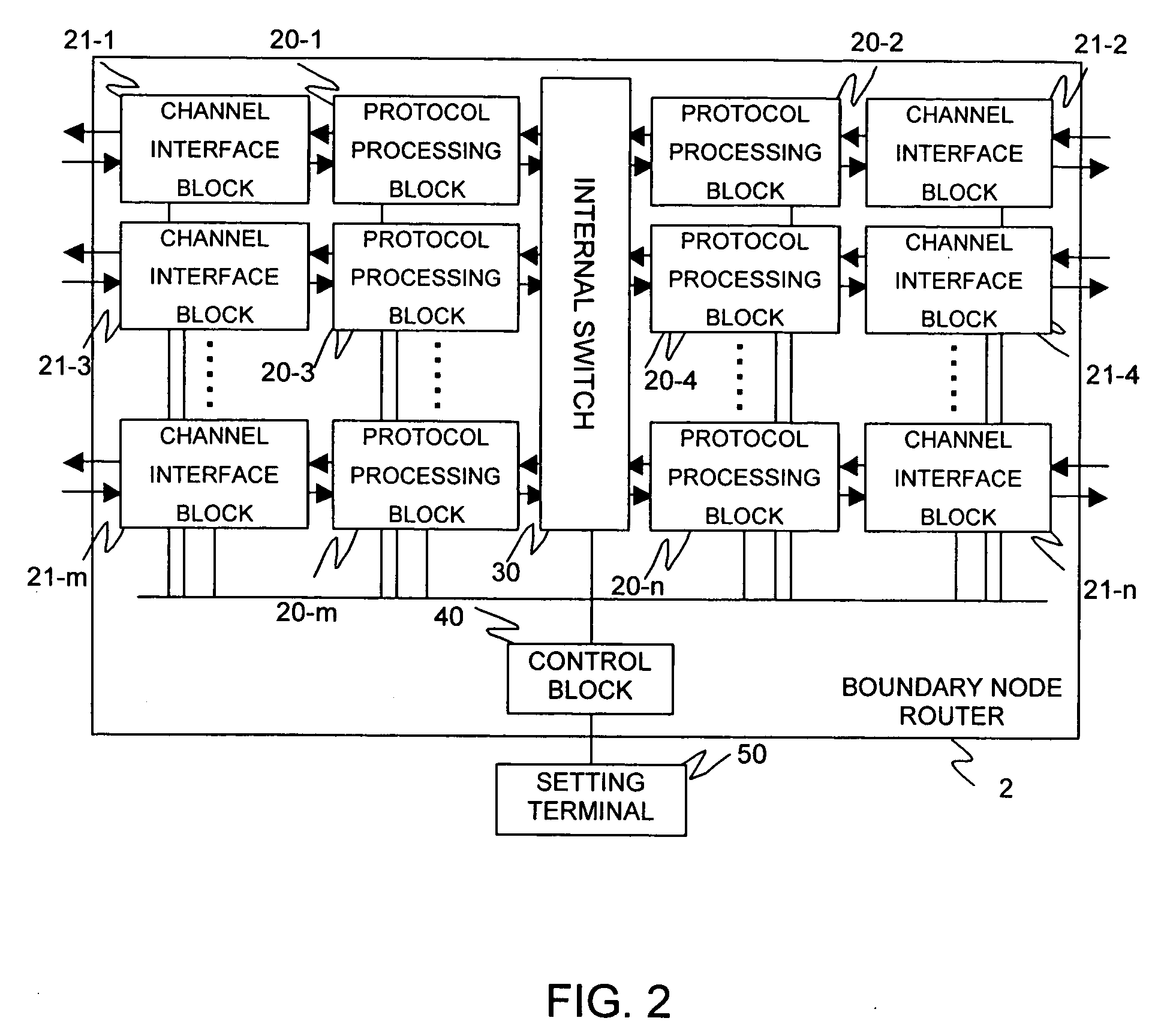
[0056]FIG. 1 is a view showing the configuration of a Diff-Serv network. The Diff-Serv network includes boundary node routers 2-1, 2-2, and 2-3 (collectively called a boundary node router 2), interior node routers 4-1 and 4-2 (collectively called an interior node router 4), and a SIP server 1.

[0057] The boundary node router 2 is disposed on a border between the Diff-Serv network and another network such as an access network. The boundary node router assigns a DSCP value and performs QoS control based on the DSCP value and others. The boundary node router 2 serves a user terminal (communication terminal) which sends at least a REGISTER message including a network user identifier and a user terminal identifier, through an access network. The boundary node router 2 performs QoS control for each user in accordance with a QoS control request from the SIP server 1.

[0058] The interior node router 4 is disposed in the Diff-Serv network a...

second embodiment

2. Second Embodiment

[0118] The boundary node router 2 of the first embodiment described above checks a message received from the user terminal 3, adds certain information to the message, and transfers the message to the SIP server 1, to update information in the SIP server 1. A boundary node router 2 of a second embodiment checks a message received from a SIP server 1, adds certain information to the message, and transfers the message to a user terminal 3, to update information in the SIP server 1 from the user terminal 3.

[0119] The second embodiment uses the same apparatus configuration and the same table configuration as the first embodiment described above, and the description of those configurations will be omitted.

[0120]FIG. 13 shows a typical message sequence for terminal authentication by the SIP protocol. First, the normal terminal authentication sequence will be described.

[0121] User terminal A 3-1 to be served by the SIP server 1 sends a REGISTER message which does not ...


PUM


Abstract

A boundary node router determines whether a received packet includes a SIP message and a REGISTER message, and, if so, adds its router identifier to a REGISTER message which includes a user identifier and a user terminal identifier, sent from a user terminal, and sends the message to a SIP server. The SIP server has a user management table which stores the user terminal identifier, the router identifier of a router which serves the user terminal, and a predetermined Quality of Service type, in association with each user identifier. The SIP server extracts a user identifier, a user terminal identifier, and a router identifier from a received REGISTER message, and updates the user terminal identifier and the router identifier corresponding to the extracted user identifier, to the extracted user terminal identifier and the extracted router identifier.

Description

BACKGROUND OF THE INVENTION [0001] 1. Field of the Invention [0002] The present invention relates to routers and Session Initiation Protocol (SIP) servers, and more specifically, to a router incorporating a technology for controlling the Quality of Service (QoS) of packets in an Internet Protocol (IP) network and a SIP server specifying the QoS of the router through the IP network. [0003] 2. Description of the Related Art [0004] As broadband access to an IP network has become widespread in recent years, applications requiring real-time capabilities such as telephony and live video distribution on the IP network have been increasing. The IP network is originally configured by a best-effort network and may not be ready for communication with near-real-time characteristics. [0005] Technologies for assuring the QoS of a network have become important, and a variety of such technologies have been standardized. One of those technologies currently used is a traffic-oriented control technolo...

Claims


Application Information

Patent Timeline
IPC IPC(8): H04L12/801H04L12/28H04L12/64H04L12/70H04L12/911H04L29/06
CPCH04L12/64
Inventor NAKAZAWA, HIROAKITACHIKAWA, ATSUSHI
Owner HITACHI LTD
Why Eureka
Try Eureka