Pan and tilt apparatus using achromatic prisms

a technology of achromatic prisms and pan and tilt, which is applied in the field of optical systems, can solve the problems of wavelength separation caused by prisms and inability to move the camera, and achieve the effect of avoiding distortion

Active Publication Date: 2005-09-29
NORTHROP GRUMMAN SYST CORP
View PDF20 Cites 25 Cited by
  • Summary
  • Abstract
  • Description
  • Claims
  • Application Information

AI Technical Summary

Problems solved by technology

In some instances, it is not practical to move the camera.
While prisms can be used to shift the direction of...

Method used


Image

  • Pan and tilt apparatus using achromatic prisms
  • Pan and tilt apparatus using achromatic prisms
  • Pan and tilt apparatus using achromatic prisms

Examples


Embodiment Construction

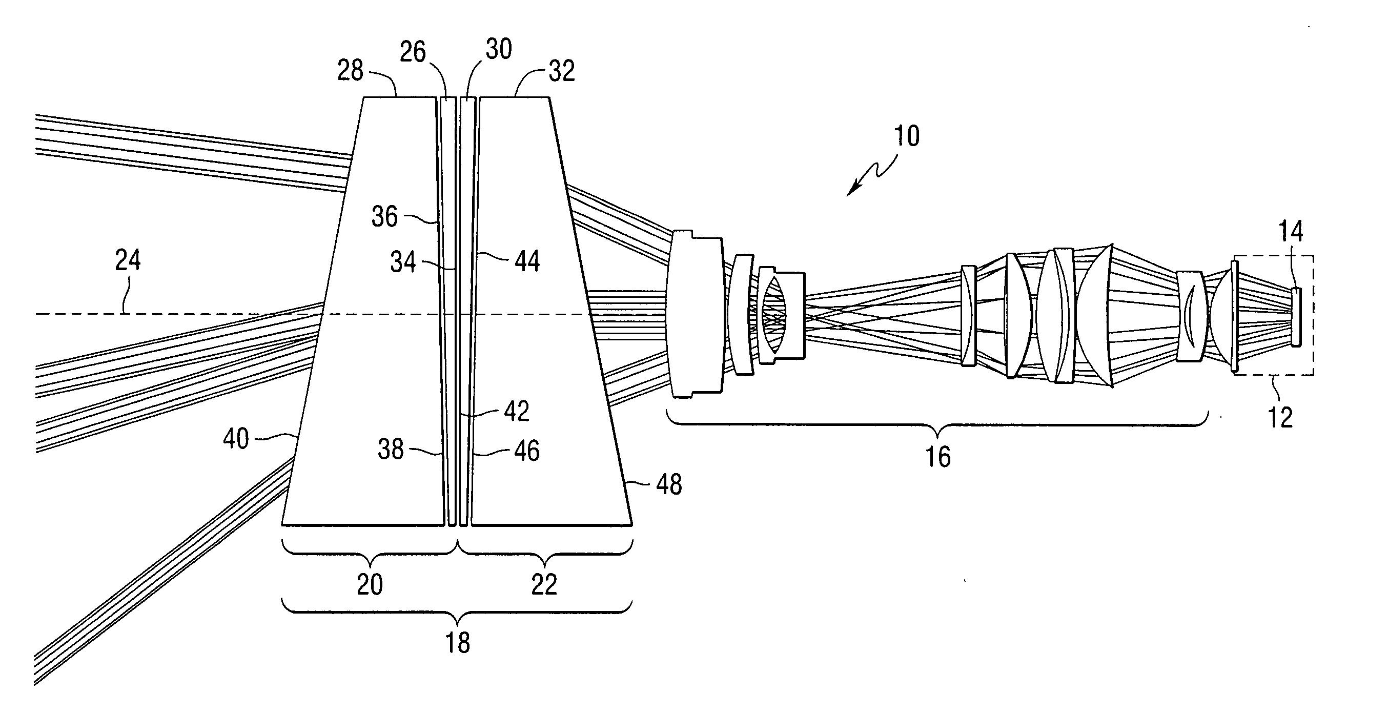
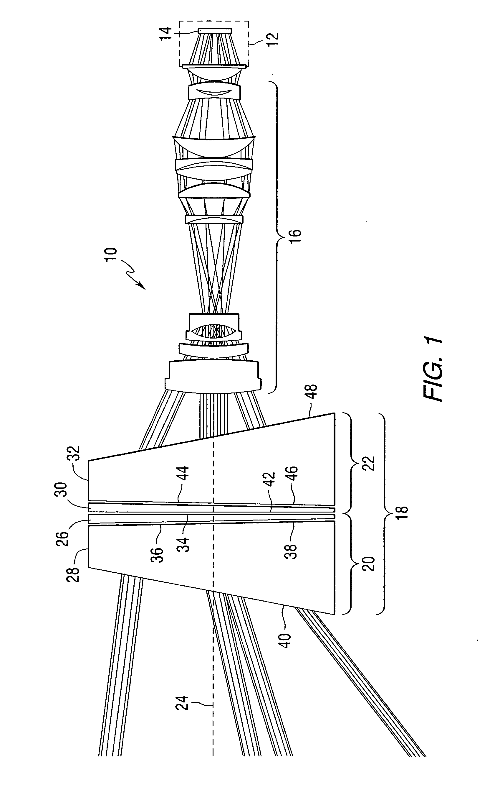
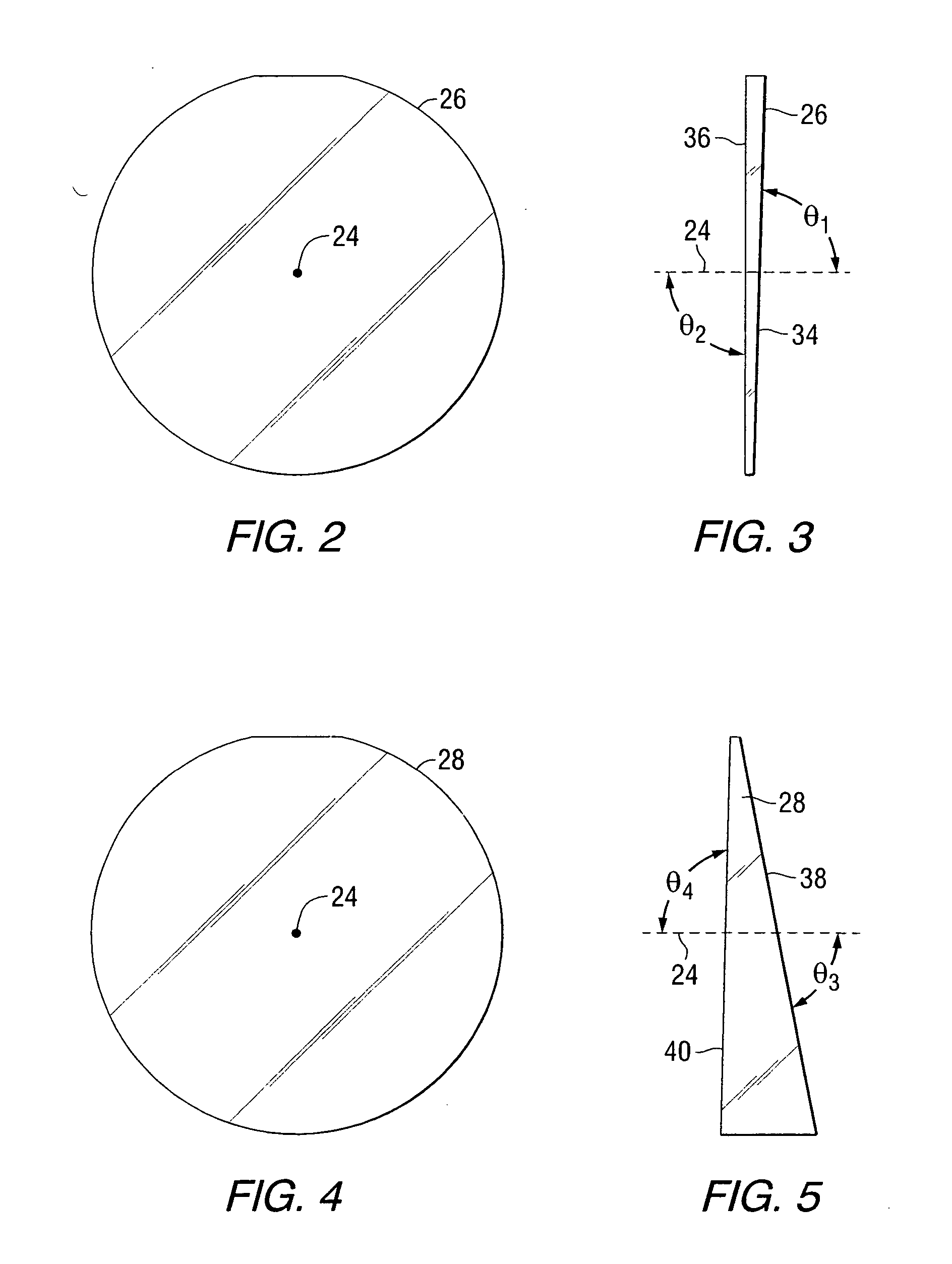
[0019] This invention accomplishes a classic pan and tilt function as would be used in a remote controlled camera or imaging application. As opposed to the normal method of pan and tilt by using a dual gimbal platform to move the entire camera, this invention accomplishes that same effect by using a pair of optical achromatically corrected prisms, rotated in opposition and in concert about a central axis to vertically and or horizontally shift the image that is captured by the camera or imaging device. Since the image may encompass the entire visible and / or infrared region, the prisms are achromatized to prevent chromatic aberrations in the final image. This invention eliminates the need for swept volume allowance in the packaging of an imaging device.

[0020]FIG. 1 is a pictorial representation of an imaging system 10 constructed in accordance with the present invention. The system includes an imaging device 12, in the form of a camera. The imaging device includes an image capture e...


PUM


Abstract

An apparatus for providing pan and tilt capability to a stationary imaging device comprises a first achromatic prism doublet positioned on a first axis, a second achromatic prism doublet positioned on the first axis, and at least one motor for rotating the first and second achromatic prism doublets about the first axis whereby polychromatic electromagnetic radiation from a portion of an area of interest is directed toward an imaging device. A method of using the apparatus is also provided.

Description

FIELD OF THE INVENTION [0001] This invention relates to optical systems, and more particularly to optical systems that provide pan and tilt functions for imaging devices. BACKGROUND OF THE INVENTION [0002] Imaging systems used for monitoring an area typically include mechanical components for moving an imaging device, such as a camera, to direct the camera toward an area of interest. The mechanical components provide a pan and tilt function and can be operated manually or automatically. In some instances, it is not practical to move the camera. For those instances, it would be desirable to have a device that provides the pan and tilt function without requiring physical movement of the camera. [0003] Prisms are known to bend light. The degree of bending is a function of the wavelength of light and thus prisms are typically used to separate the various light wavelengths allowing independent studying of each wavelength of the incident light beam. In the case of white light, comprised o...

Claims


Application Information

Patent Timeline
IPC IPC(8): G02B26/08G03B11/00G03B17/56
CPCG03B17/56G02B26/0891G03B15/00G03B17/565
Inventor KREGER, JAMES HARRISONFOLBERTH, PETER JAMES
Owner NORTHROP GRUMMAN SYST CORP
Why Eureka
Try Eureka