Electronic part-mounting socket

a technology of electronic parts and sockets, applied in the field of sockets, can solve the problems of increasing the size of the outer surface, increasing the cost of the mold, and preventing the achievement of compact design, and achieve the effect of low cost production

Inactive Publication Date: 2005-09-29
SMK CORP
View PDF9 Cites 18 Cited by
  • Summary
  • Abstract
  • Description
  • Claims
  • Application Information

AI Technical Summary

Benefits of technology

[0007] In view of the problems of the above related technique, it is an object of this invention to provide...

Problems solved by technology

Therefore, the outer size increased, and this prevented the achievement of a compact design.
In such a structure, there was encountered a pro...

Method used


Image

  • Electronic part-mounting socket
  • Electronic part-mounting socket
  • Electronic part-mounting socket

Examples


Embodiment Construction

[0049] An electronic part-mounting socket according to the present invention will now be described with reference to FIGS. 1 to 13. Identical portions to those of the above example will be designated by identical reference numerals, respectively, and explanation thereof will be omitted.

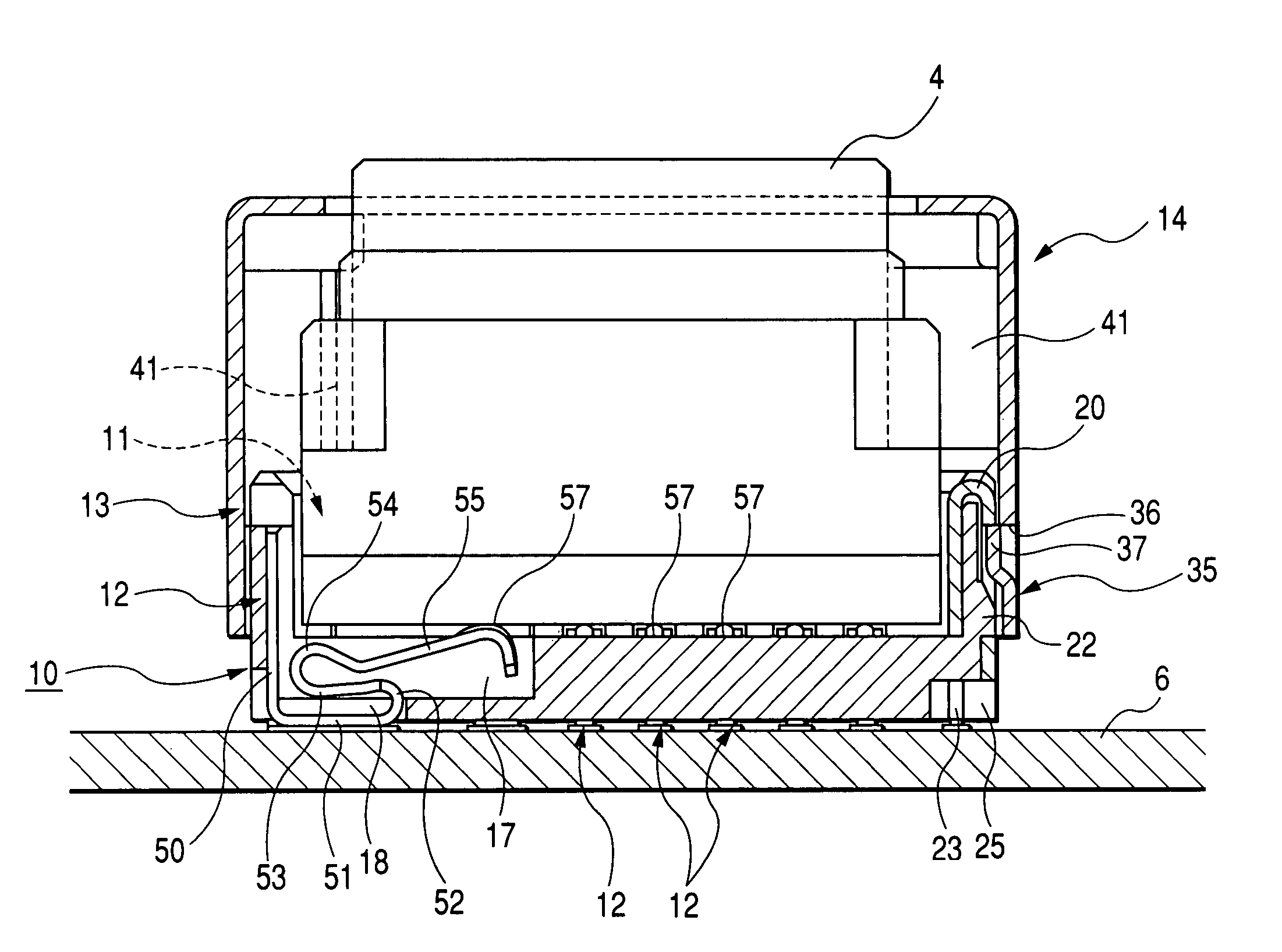
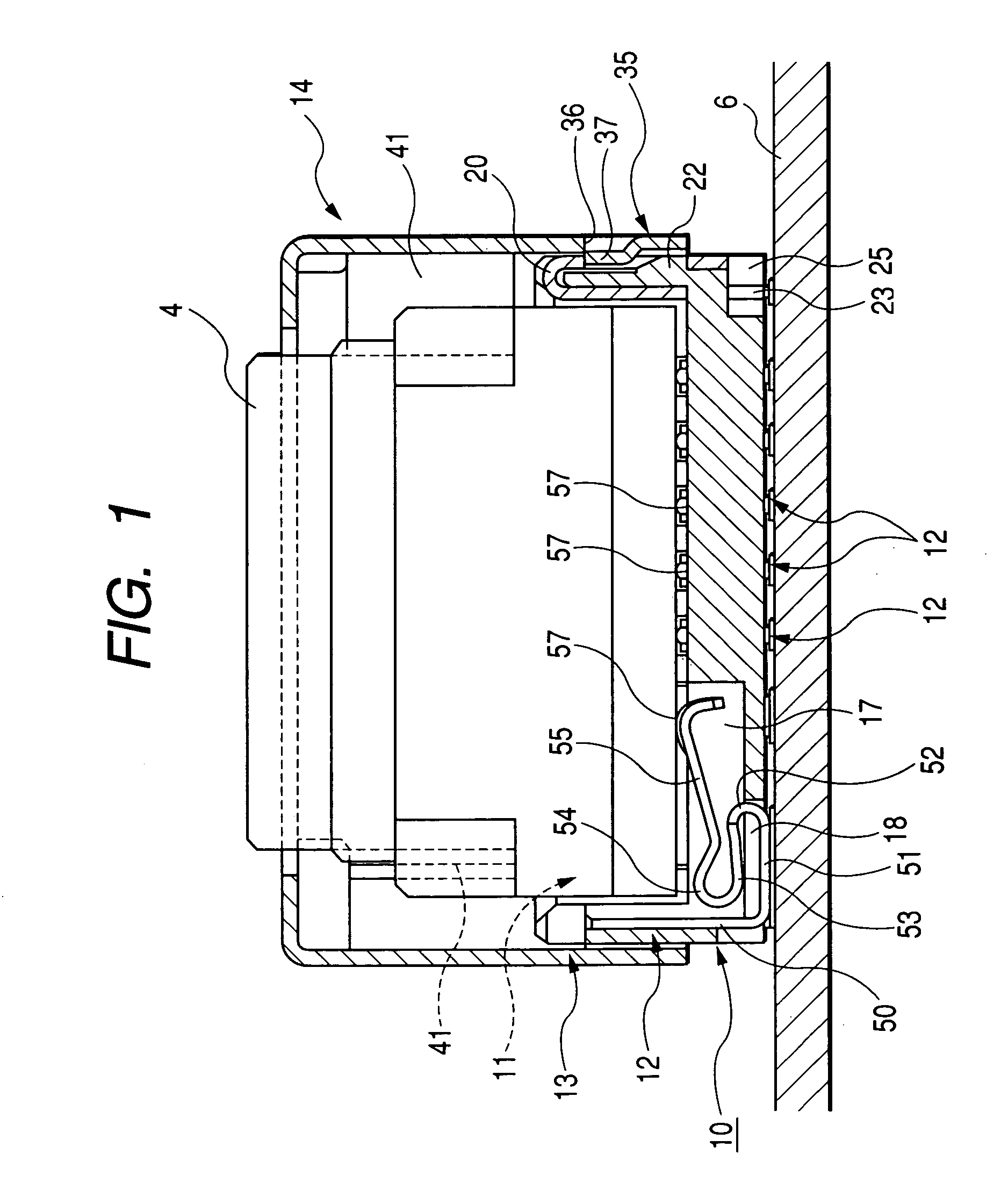
[0050]FIG. 1 shows a condition of use in which an electronic part such as a camera module is mounted on a printed wiring board through the electric part-mounting socket. In the drawings, reference numeral 10 denotes the electronic part-mounting socket, reference numeral 4 the camera module, and reference numeral 6 the printed wiring board.

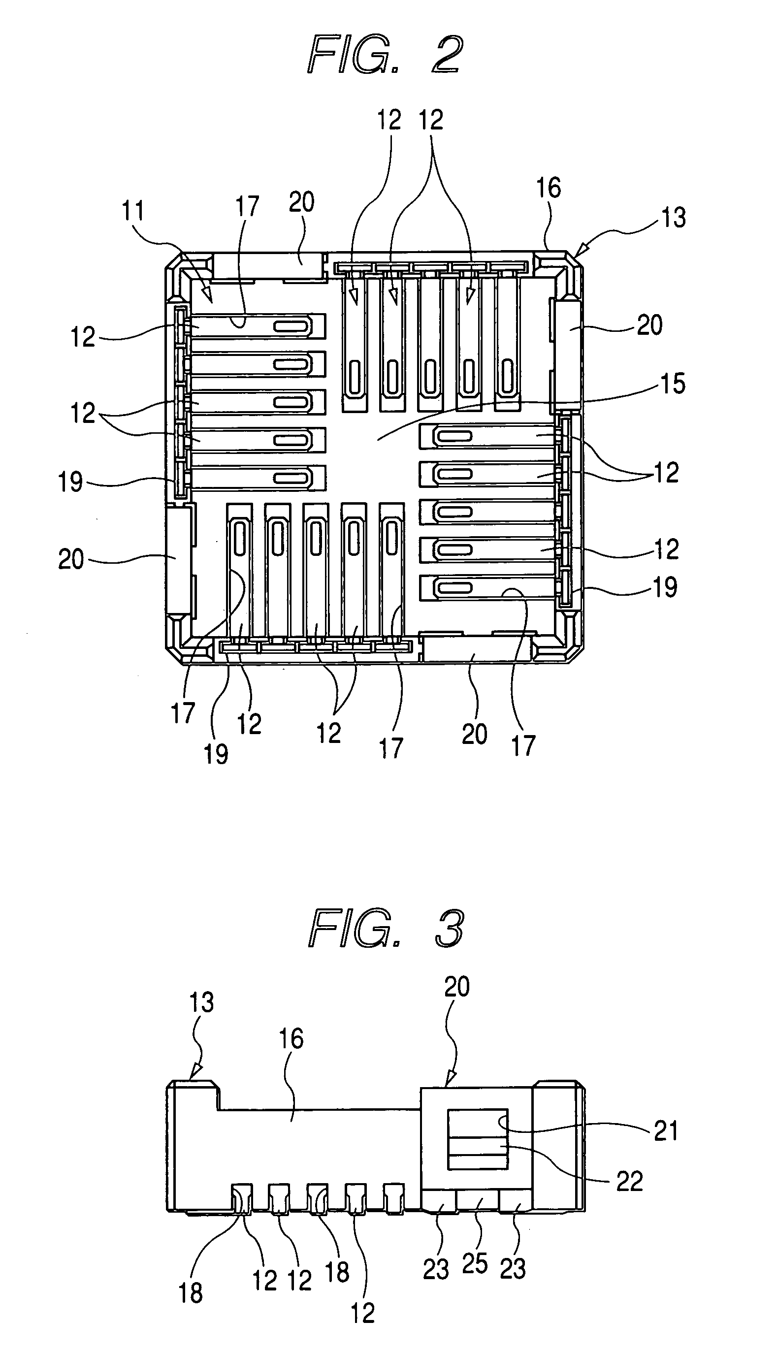
[0051] The electronic part-mounting socket 10 includes a socket housing 13 having an electronic part-receiving portion 11 with an open top for receiving part or the whole of the electronic part 4, and a plurality of contacts 12 supported on the socket housing 13. The electronic part 4, when received in the electronic part-receiving portion 11, is connected to the p...


PUM


Abstract

An electronic part-mounting socket includes a socket housing, and contacts The socket housing has contact receiving grooves formed at a bottom plate portion of an electronic part-receiving portion. The contact of an integral construction includes a fixing piece portion, a terminal piece portion laterally bent at a lower end of the fixing piece portion, a first bent-back portion formed by bending back a distal end portion of the terminal piece portion into a U-shape, an intermediate spring piece portion extending laterally from the first bent-back portion, a second bent-back portion formed by bending back a distal end portion of the intermediate spring piece portion into a U-shape, and a resilient contact piece portion extending continuously from the second bent-back portion in an upwardly-slanting manner. The fixing piece portions are inserted respectively in contact fixing holes, formed in the socket housing in an upward-downward direction, and are fixed thereto.

Description

BACKGROUND OF THE INVENTION [0001] This invention relates to a socket for mounting an electronic part, mainly such as a camera module, on a printed wiring board. [0002] Generally, an electronic device, such as a cellular phone, has a printed wiring board provided therein, and an electronic part such as a camera module is mounted on the printed wiring board. The electronic part, having a low degree of heat tolerance, can not be directly mounted on the board by soldering, and therefore is connected to the printed wiring board, using an electronic part-mounting socket as shown in FIG. 14. [0003] This electronic part-mounting socket 1 is constituted by a socket housing 3 having an electronic part-receiving portion 2 formed by a peripheral wall extending upwardly from four sides of a square bottom plate, and a plurality of contacts 5 each having a resilient contact piece portion 5a which projects from the bottom plate so as to be resiliently contacted with a corresponding terminal portio...

Claims


Application Information

Patent Timeline
IPC IPC(8): H01R12/00H01R13/24H01R12/70H01R12/71H01R13/41H01R13/658H01R13/6582H01R13/6594H01R33/00H01R33/76H05K7/10
CPCH01R13/2442H01R13/41H05K7/1069H01R13/6594H01R12/716H01R13/6582H01R12/707H01R33/76
Inventor ASAI, KIYOSHIKANAZAWA, KAZUAKIKOBAYASHI, JUNICHI
Owner SMK CORP
Why Eureka
Try Eureka