Centrifugal pump fuel system and method for gas turbine engine

a technology of centrifugal pump and fuel system, which is applied in the direction of process and machine control, fluid pressure control, instruments, etc., can solve the problems of adding substantial weight, size, and expense, and not providing a predetermined flow rate based on centrifugal pump

Inactive Publication Date: 2005-10-06
WOODWARD GOVERNOR CO
View PDF11 Cites 66 Cited by
  • Summary
  • Abstract
  • Description
  • Claims
  • Application Information

AI Technical Summary

Benefits of technology

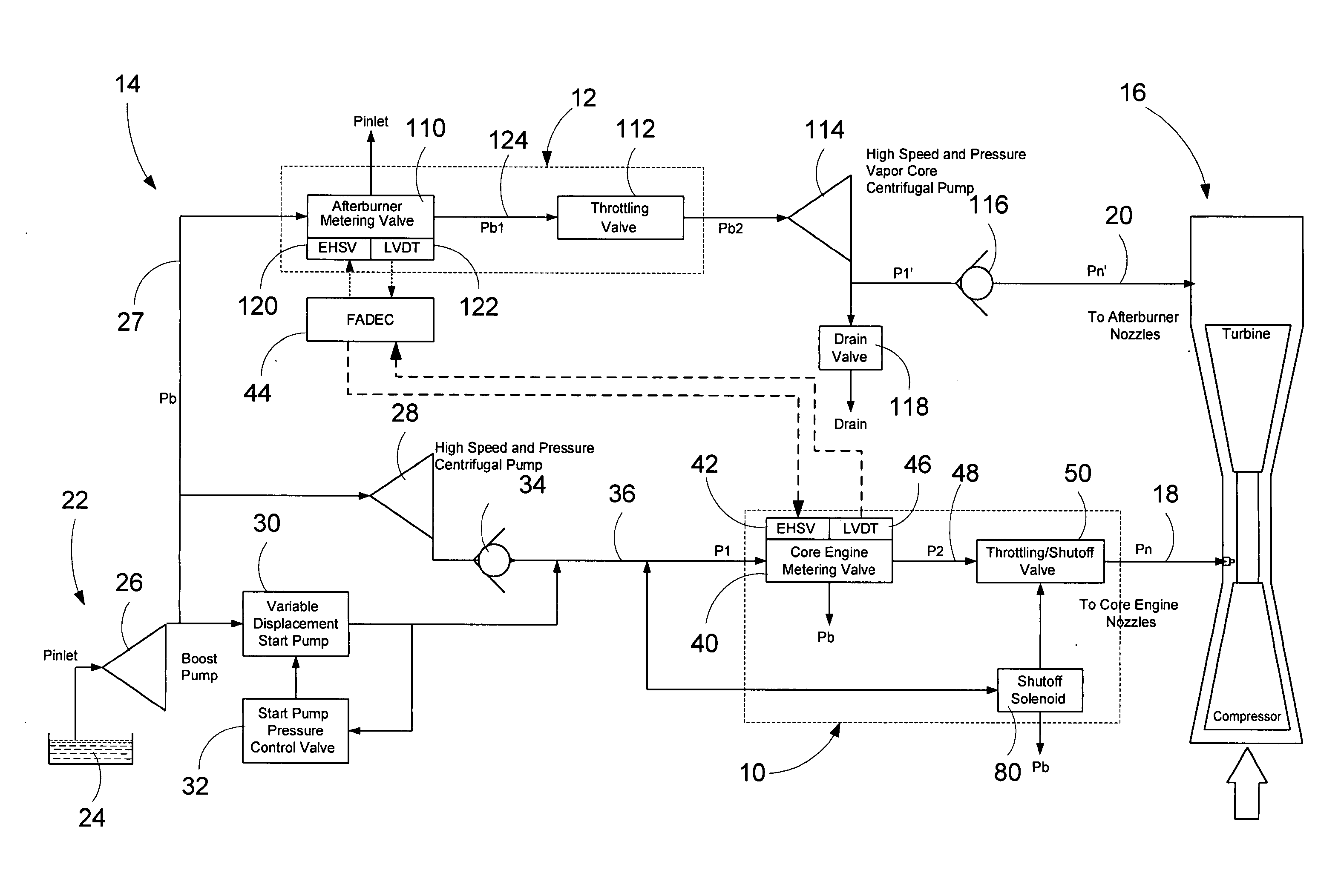
[0010] It is a further aspect of the present invention that the throttle valve includes a multiple diameter valve piston slidable in a valve body. The valve piston comprises working surfaces of at least two different diameters such that changes in chamber pressures effect different axial forces upon the piston. The valve piston may comprise first and second lands in spaced axial relation such that the throttle valve defines at least three chambers, including a first chamber subjected to fluid pressure upstream of the fuel metering valve, a second chamber subjected to fluid pressure downstream of the fuel metering valve, and the compensation chamber intermediate of the two variable orifices. The compensation chamber is arranged in fluidic series with the fuel metering valve and the nozzle outlet passage whereby fuel flows through the compensation chamber to the nozzle outlet passage.
[0011] It is an advantage that the compensation chamber may be used to counteract variances in forces that can occur due to changes in valve position. For example the valve experiences different amounts of fluid flow forces (namely, Bernoulli forces) and spring forces at different valve positions. Changes in fluid pressure in the compensation chamber can be designed to compensate for changes in spring forces and / or naturally occurring fluid forces such as Bernoulli forces that may be generated by fluid flowing through the throttle valve.

Problems solved by technology

Centrifugal pumps, by contrast do not provide a predetermined flow rate based upon speed.
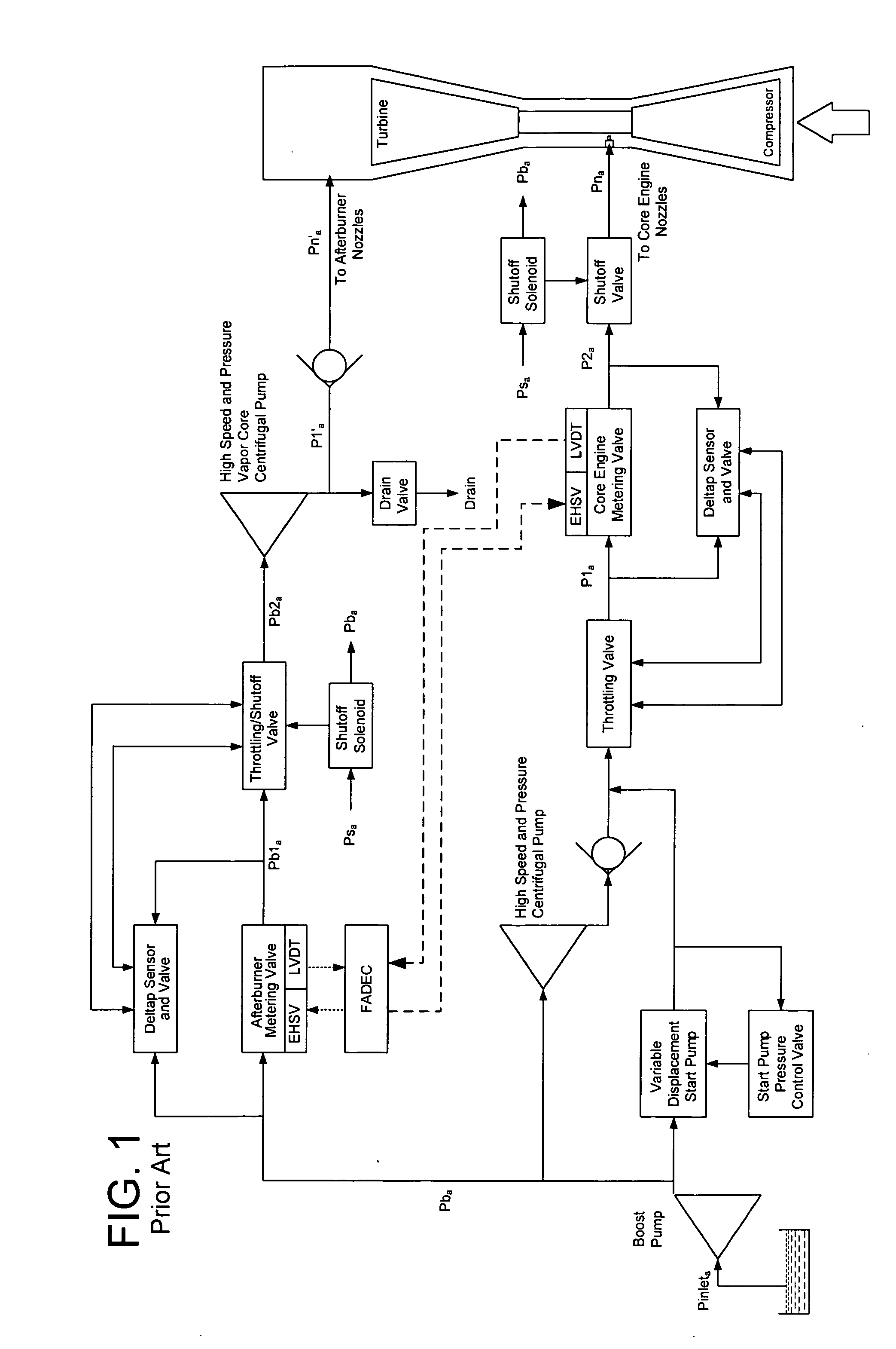
Unfortunately, incorporating the plumbing, multiple stages, valves and sensors to provide accurate control over metering valve pressure drop accuracy such as that schematically illustrated in FIG. 1 has added substantial weight, size, and expense.
It has also reduced dynamic performance, stability and the reliability of centrifugal pump metering systems.
These are all disadvantages, particularly in aircraft applications where there is always a constant desire to reduce weight while maintaining or increasing performance and reliability.

Method used


Image

  • Centrifugal pump fuel system and method for gas turbine engine
  • Centrifugal pump fuel system and method for gas turbine engine
  • Centrifugal pump fuel system and method for gas turbine engine

Examples


Embodiment Construction

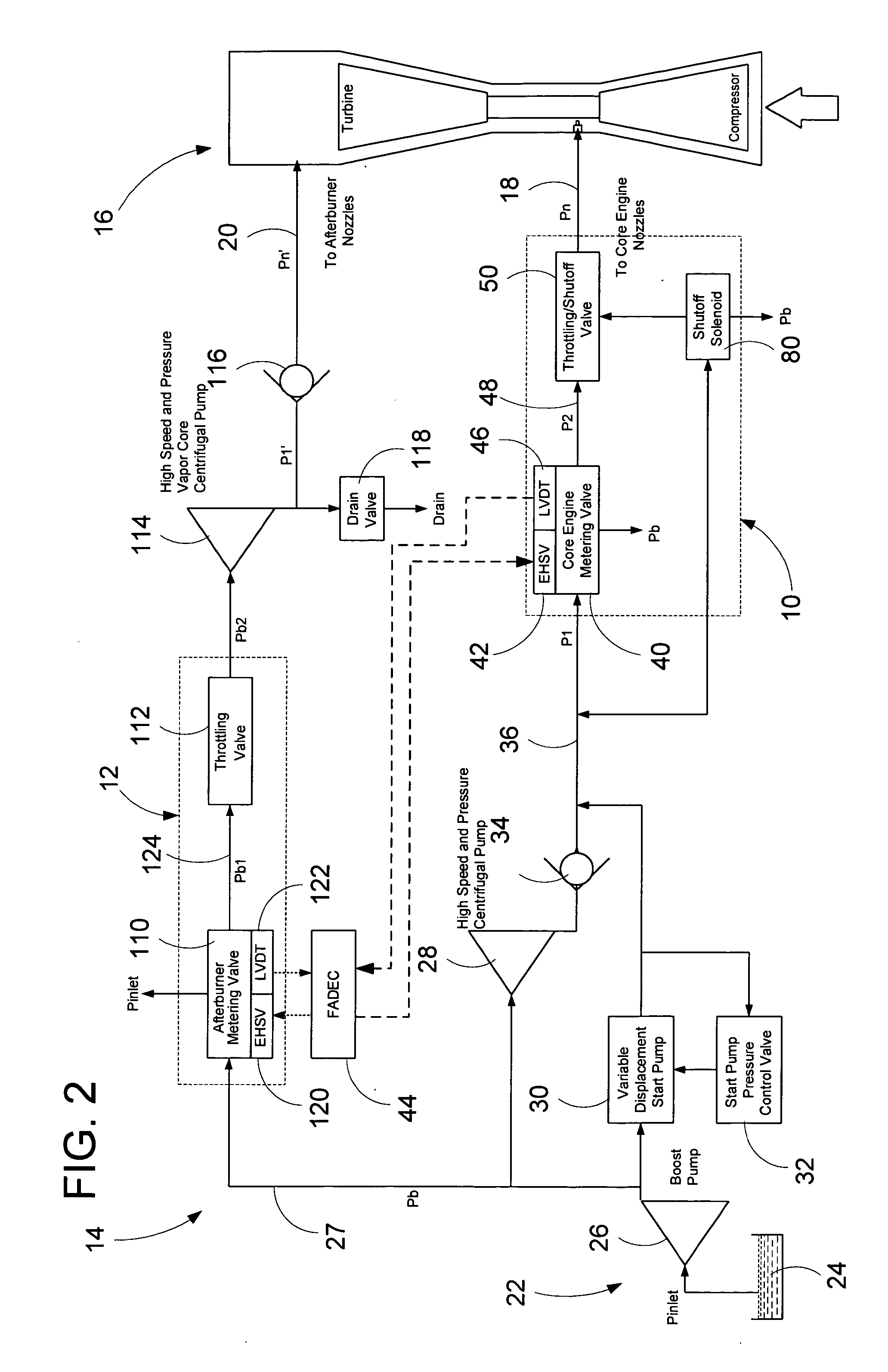
[0020] Referring to FIG. 2, two different fuel metering units 10, 12 according to two different embodiments of the present invention are illustrated for a fuel delivery system 14 for a gas turbine engine 16 according to an embodiment of the present invention. One of the fuel metering units 10 meters core engine fuel flow and is arranged to control primary fuel flow along a nozzle outlet passage 18 leading to nozzles that discharge into the core of the gas turbine engine 16. The other fuel metering unit 12 meters afterburner fuel flow and is arranged to control fuel flow through a nozzle passage 20 leading to afterburner nozzles. As illustrated, the main fuel metering unit 10 and the after burner unit 12 are arranged in a parallel fluid circuit. It will be appreciated that many aircraft and gas turbine engines do not include afterburner systems, and the invention is applicable and covers these fuel delivery systems as well.

[0021] The fuel delivery system 14 includes a fuel supply 22...


PUM


Abstract

A fuel system for a gas turbine engine that utilizes a centrifugal pump is presented. The system includes a fuel metering valve that is adapted to set a metered flow of fuel, and a throttle valve that is adapted to accurately control pressure drop across the fuel metering valve. The throttle valve has at least two variable orifices and a compensation chamber between the variable orifices. The throttle valve includes a differential valve piston slidable in a valve body. The differential valve piston comprises working surfaces of at least two different diameters such that changes in chamber pressures effect different axial forces upon the piston.

Description

CROSS-REFERENCE TO RELATED PATENT APPLICATIONS [0001] This patent application is a divisional of copending U.S. patent Ser. No. 10 / 463,701, filed Jun. 16, 2003.FIELD OF THE INVENTION [0002] This invention pertains to gas turbine fuel systems and more particularly to gas turbine fuel systems that use high pressure centrifugal pumps. BACKGROUND OF THE INVENTION [0003] There are two types of high pressure fuel pumping systems for gas turbine engines. The first type utilizes a positive displacement pump (typically a gear pump). The other type utilizes a centrifugal pump. The fuel metering units for these types of fuel systems are substantially different in design, application and practice due to the fact that positive displacement pumps provide a predetermined flow rate based on pump speed (a flow generation source), whereas a centrifugal system generates pressure (a pressure generation source) proportional to pump speed squared. [0004] Examples of positive displacement pump fuel meteri...

Claims


Application Information

Patent Timeline
Patent Type & Authority Applications(United States)
IPC IPC(8): F02C7/22F02C7/232F02C7/236F02C9/00F02C9/26F02C9/28F02C9/30F02C9/32
CPCF02C7/232F02C7/236Y02T50/671F02C9/30F02C9/32F02C9/263Y02T50/60Y10T137/87917
Inventor WERNBERG, DONALD E.SCHAEFER, PAUL J.HOMMEMA, EDWARD L.
Owner WOODWARD GOVERNOR CO
Why Eureka
Try Eureka