Hydrostatic displacer unit with a pivoting mechanism and a servo unit having pressure-reducing valves

Inactive Publication Date: 2005-10-06
SAUER DANFOSS NORDBERG
View PDF8 Cites 0 Cited by
  • Summary
  • Abstract
  • Description
  • Claims
  • Application Information

AI Technical Summary

Benefits of technology

[0012] By means of the invention, a hydrostatic displacer unit with a servo system is to be provided, which allo

Problems solved by technology

The disadvantage of this is that pressure-reducing valves even of the same type of construction are never identical because of unavoidable spring-force tolerances and fluctuations in the dimensions of the installation spaces.
Another disadvantage is that, conventionally, a sufficientl

Method used


Image

  • Hydrostatic displacer unit with a pivoting mechanism and a servo unit having pressure-reducing valves
  • Hydrostatic displacer unit with a pivoting mechanism and a servo unit having pressure-reducing valves

Examples


Example

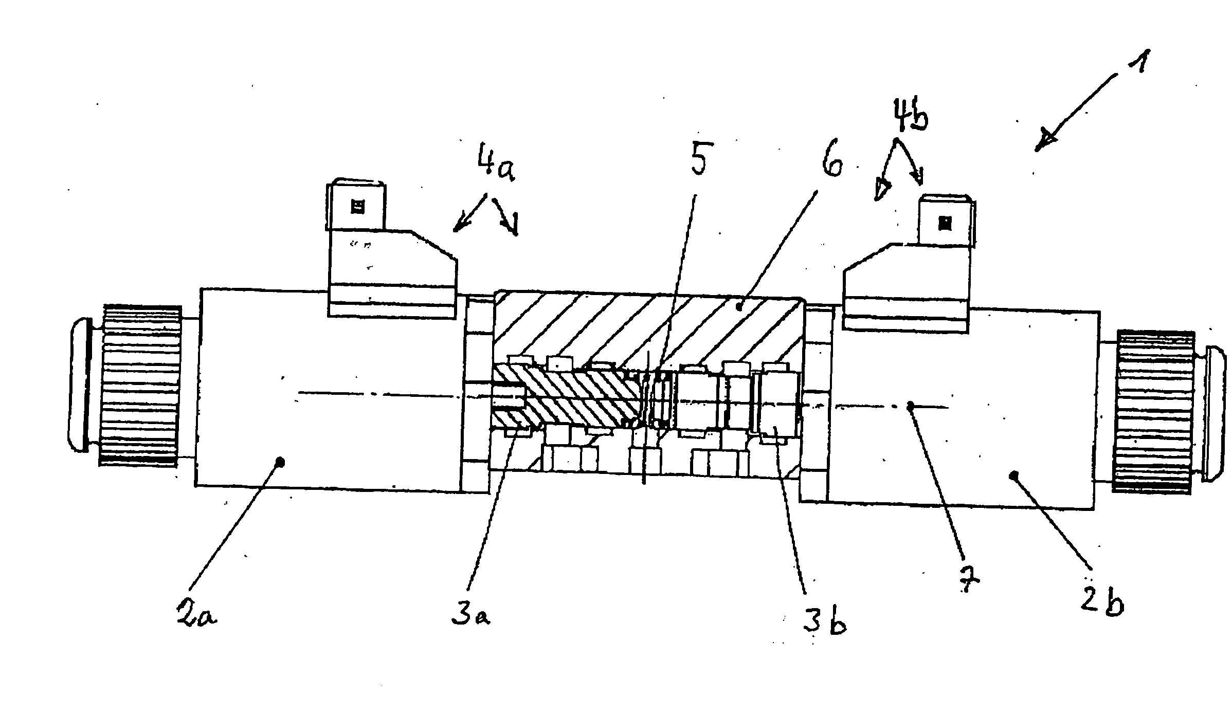
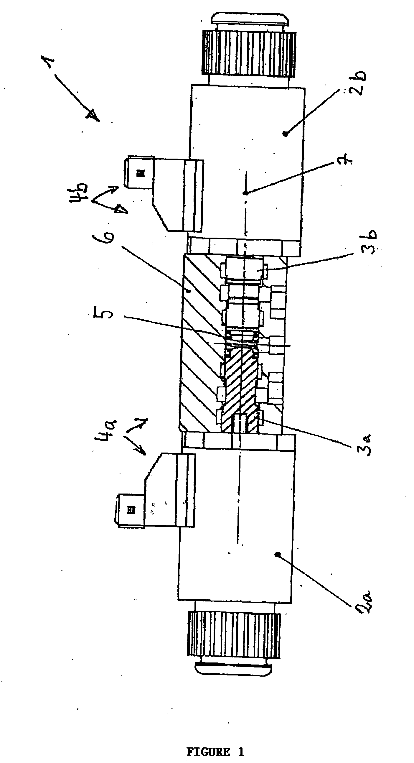
[0022] The FIGURE illustrates an adjusting device 1 for the servo system of a hydrostatic displacer unit according to the invention. It consists in each case, for each conveying direction, of an electrically activatable proportional magnet 2a, 2b which, together with a control piston 3a, 3b in each case, forms an electrically activatable pressure-reducing valve 4a, 4b. The FIGURE in this case shows the control piston 3a in section, whilst the control piston 3b is illustrated non-sectionally.

[0023] The spring arrangement 5 consists, in the version according to the FIGURE, of a compression spring which is arranged between the ends of the control pistons 3a, 3b along their common axis of movement 7. The spring is prestressed by means of the available construction space and has the task of holding the control pistons 3a, 3b in their initial positions which are afforded on both sides in each case by a stop against which the respective control piston is pressed by the spring. When a suff...


PUM


Abstract

The invention relates to a hydrostatic displacer unit with a pivoting mechanism for two conveying directions for the continuous variation of the stroke of displacement pistons and with a servo system by means of which the pivoting mechanism can be moved in opposite pivoting directions. The servo system comprises at least two servocylinders, by means of which servopjstons which actuate the pivoting mechanism can be moved, and an adjusting device in each case with a pressure-reducing valve for each servocylinder. The control pistons of the pressure-reducing valves are coupled mechanically along a common axis of movement by means of a spring arrangement.

Description

BACKGROUND OF THE INVENTION [0001] The invention relates to a hydrostatic displacer unit with a pivoting mechanism and a servo system having pressure-reducing valves according to the precharacterizing clause of Patent Claim 1. [0002] Hydrostatic displacer units with a pivoting mechanism for two conveying directions for the continuous variation of the stroke of displacement pistons have devices by means of which the stroke volume can be varied in a controlled or regulated way. These devices are combined in all their subassemblies under the term “servo system”. So that, by means of the servo system, the pivoting mechanism can be moved in opposite directions and the volume flow can be varied accordingly, the servo system typically comprises at least two servocylinders which are each assigned a servopiston actuating the pivoting mechanism. The servo system may also be designed in such a way that a common servopiston movable in opposite directions is provided between two servocylinders a...

Claims


Application Information

Patent Timeline
IPC IPC(8): F04B1/32F15B13/044
CPCF04B1/328F03C1/0694Y10T137/87217
Inventor THOMS, REINHARDT
Owner SAUER DANFOSS NORDBERG
Why Eureka
Try Eureka