Connector and tubing assembly and method of molding connector and tubing assembly

Active Publication Date: 2019-01-10
SANI TECH WEST INC
View PDF0 Cites 3 Cited by
  • Summary
  • Abstract
  • Description
  • Claims
  • Application Information

AI Technical Summary

Benefits of technology

The present invention is a method and device design that uses a molding operation to fasten a plurality of tubes to one or more fittings. The molding material does not form the flow path, but instead the tubes are securely connected to the fittings with fluid-tight seals and smooth transition between the inner diameters of the connector and tubes. This invention eliminates the need for inner molding pieces and passage-forming assemblies of the prior art, which can lead to contamination and wall damage inside the fluid path. The connector piece provides strength and resistance against the pressure of the molding operation. The respective geometries of the connector piece and tubes provide a seal against molding material entering the pre-established fluid path. The molded layer of thermoplastic or polymeric material disposed about at least a portion of the connector member and the terminal portion of the at least one tube enhances bonding of the connector member to the layer of thermoplastic or polymeric material. The invention also allows for better continuity or smooth transition of the inner-diameter lumen surfaces of the connector member and the tubes. The connector members can be tapered with larger ends having the projecting structures engaging another connector member and the smaller ends inserted into the tubes, which facilitates certain flow patterns during the manufacture of medicaments.

Problems solved by technology

Because these systems were capital intensive, drug manufacturers would go to large expense to validate cleanability and ensure no cross contamination from one batch to the next.
Facility owners have had to invest in expensive large and sophisticated utility plants with chemical dosing systems and ultra-high purity steam systems necessary to sterilize the systems.
For less critical applications, methods can be as simple as a nylon cable tie or stainless crimp ring over a hose end that has a barbed fitting inserted (“tube to hose barb” connection) but for the most critical applications this type of connection may present too much risk to seal integrity.
There are many drawbacks to the existing methods, which rely on several invasive steps in the manufacturing process, presenting high risk of potentially contaminating or damaging the interiors of the tubes.
In addition, current methods are limited in the interior shape of the flow path because of the necessity of removing the temporary inserts around which the flow path is molded.

Method used


Image

  • Connector and tubing assembly and method of molding connector and tubing assembly
  • Connector and tubing assembly and method of molding connector and tubing assembly
  • Connector and tubing assembly and method of molding connector and tubing assembly

Examples


Embodiment Construction

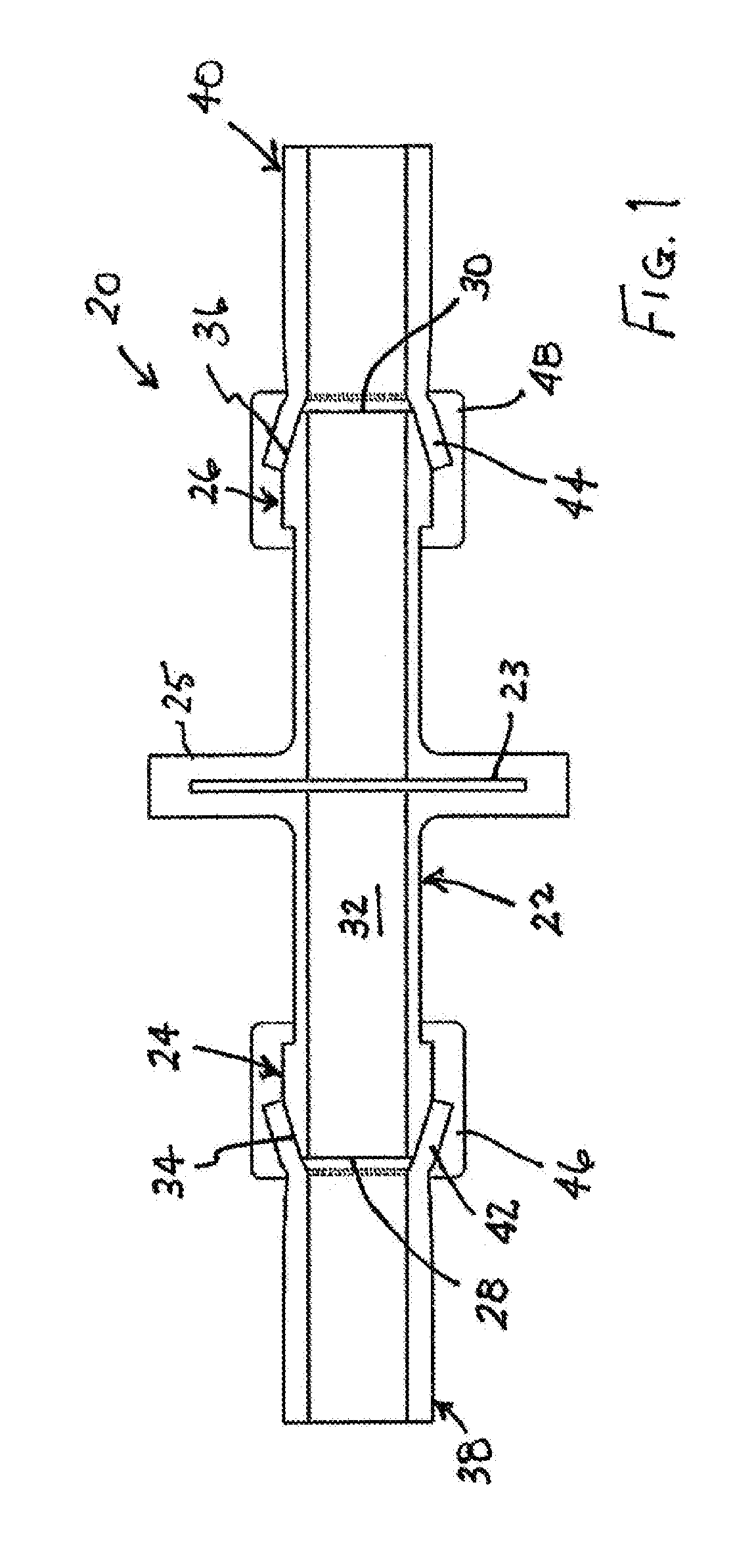
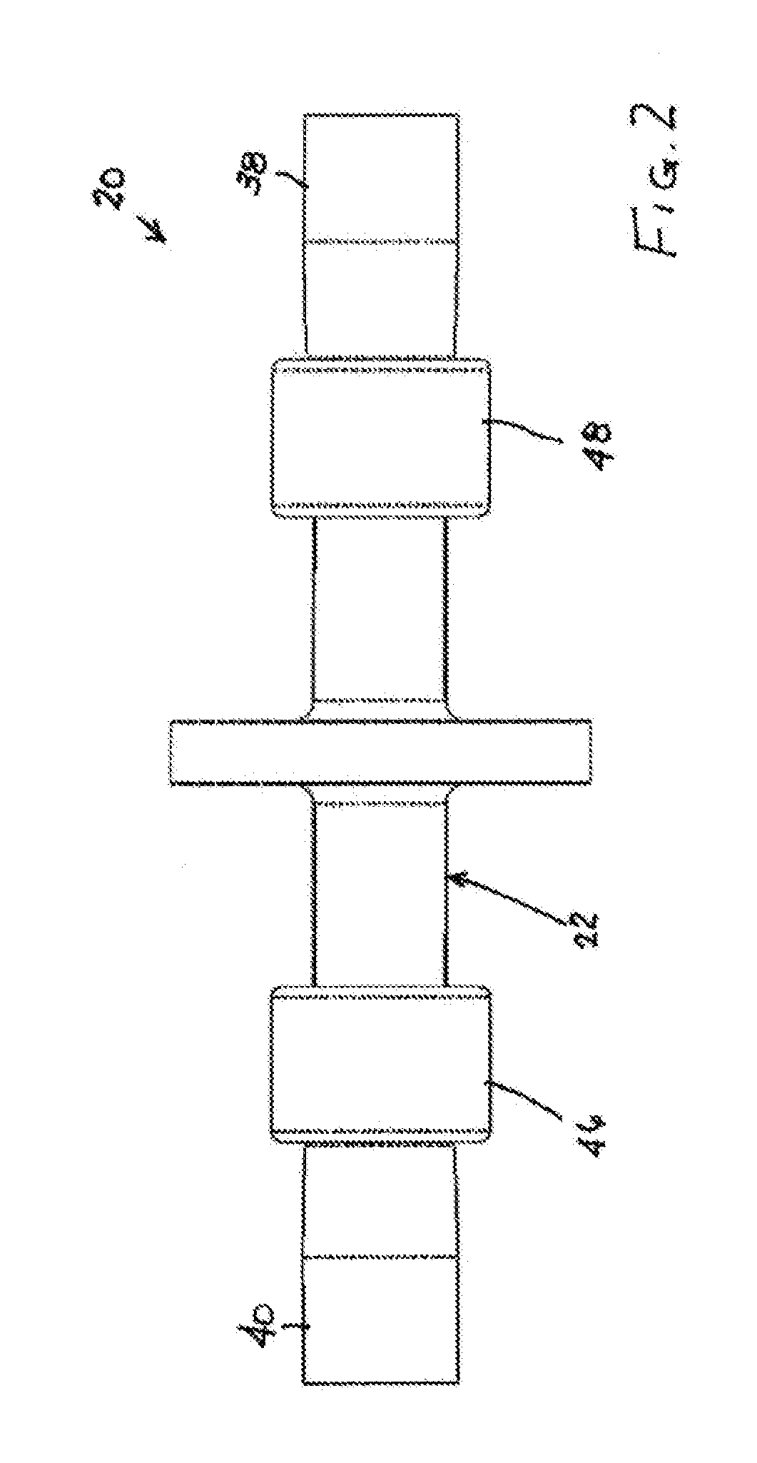
[0042]As depicted in FIGS. 1 and 2, a connector and tubing assembly 20 comprises a preformed connector member or fitting element 22 incorporating a filter element 23 within a flange 25 and having a pair of ends 24 and 26 with respective openings 28 and 30 that communicate with one another through a lumen 32 of the connector member. Connector or inline filter member 22 is formed at each of end 24 and 26 with a respective tapered or conical structure 34 and 36 extending radially outwardly from an outer surface 37 of the connector member. Two tubes 38 and 40, which are equal in number to the ends 24 and 26 of the connector member 22, each have a terminal portion 42 and 44. Ends 24 and 26 of connector member 22 are each inserted into the terminal portion 42 and 44 of a respective tube 38 and 40 so that the respective terminal portion is deformed to flare outwardly, as shown in FIG. 1. A layer of thermoplastic or polymeric material is molded in separate amounts or aliquots at respective ...


PUM

PropertyMeasurementUnit
Moldableaaaaaaaaaa

Abstract

An overmolding method for forming joints in a fluid-flow apparatus utilizes a connector or fitting as a component for mold forming. The connector or fitting is not removed after the overmolding and thus forms part of the joint assembly.

Description

FIELD OF THE INVENTION[0001]The invention relates to tubing systems used to transport fluidic materials in the manufacture, for instance, of pharmaceuticals and medicaments. This invention more particularly relates to methods of manufacturing such tubing systems and particularly connection or joint assemblies thereof.BACKGROUND OF THE INVENTION[0002]For as long as drug products have been manufactured, the Biotech and Pharmaceutical industry used various methods to convey liquid products during the drug manufacturing process. In more recent years the industry's mindset has been to move away from traditional processes which relied on fixed capital intensive piping systems. Traditional systems are typically made from stainless steel or glass lined piping. Because these systems were capital intensive, drug manufacturers would go to large expense to validate cleanability and ensure no cross contamination from one batch to the next. Facility owners have had to invest in expensive large an...

Claims


Application Information

Patent Timeline
IPC IPC(8): B29C70/84A61M39/08A61M39/12
CPCB29C70/845A61M39/08A61M2207/00B29L2023/00A61M39/12B29C65/70B29L2031/246B29C66/1162B29C66/5221B29C66/52241B29C66/7392F16L47/02F16L47/32F16L41/021B01D46/0012
Inventor DUPONT, JR., PAUL ROBERTMCKIERNAN, KEVIN
Owner SANI TECH WEST INC
Why Eureka
Try Eureka