Method of Manufacturing A Wind Turbine Blade

Active Publication Date: 2019-06-13
LM WP PATENT HLDG
View PDF3 Cites 2 Cited by
  • Summary
  • Abstract
  • Description
  • Claims
  • Application Information

AI Technical Summary

Benefits of technology

[0062]Thereby, a gradual transition is obtained between the opposite walls of the preformed shell member and the integrated main laminate or spar cap, and the risk of stress concentrations is reduced
[0063]The lay-up of the secondary fibre m

Problems solved by technology

Ensuring a complete distribution of the polymer in the entire mould cavity is, however, often difficult, and accordingly, this often results in so-called dry spots, i.e. areas with fibre material not being sufficiently impregnated with resin.
Thus, dry spots are areas where the fibre material is not impregnated, and where there can be air pockets, which are difficult or impossible to remove by controlling the vacuum pressure and a possible overpressure at the inlet side.
This is a time-consuming and tiresome process.
This is not desirable, especially not when the polymer has not hardened, as it can result in deformations in the inserted fibre material and thus in a local weakening of the structure, which can cause for instance buckling effects.
Th

Method used


Image

  • Method of Manufacturing A Wind Turbine Blade
  • Method of Manufacturing A Wind Turbine Blade
  • Method of Manufacturing A Wind Turbine Blade

Examples


Embodiment Construction

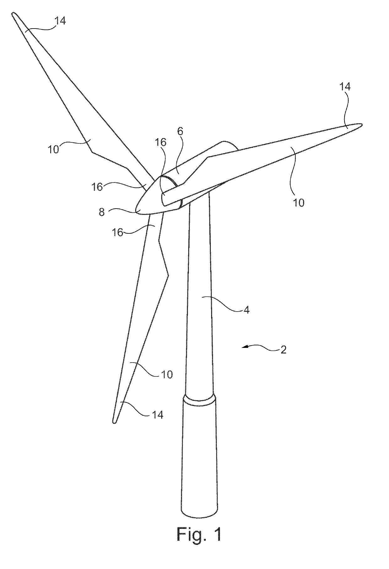
[0082]FIG. 1 illustrates a conventional modern upwind wind turbine according to the so-called “Danish concept” with a tower 4, a nacelle 6 and a rotor with a substantially horizontal rotor shaft. The rotor includes a hub 8 and three blades 10 extending radially from the hub 8, each having a blade root 16 nearest the hub and a blade tip 14 farthest from the hub 8. The rotor has a radius denoted R.

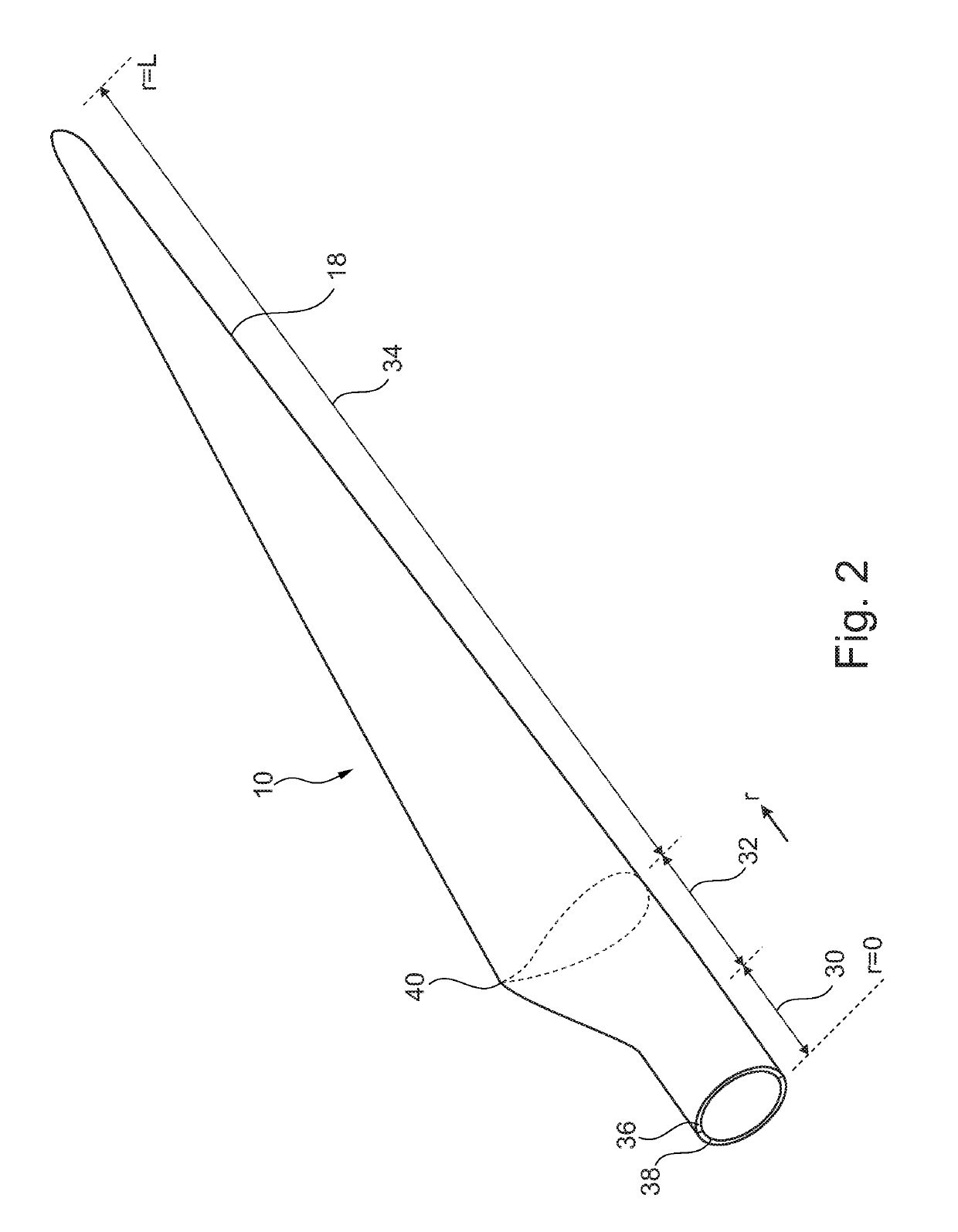
[0083]FIG. 2 is a schematic view of an embodiment of a wind turbine blade 10 manufactured by the method according to the invention. The wind turbine blade 10 has the shape of a conventional wind turbine blade and comprises a root region 30 closest to the hub, a profiled or an airfoil region 34 farthest away from the hub and a transition region 32 between the root region 30 and the airfoil region 34. The blade 10 comprises a leading edge 18 facing the direction of rotation of the blade 10, when the blade is mounted on the hub, and a trailing edge 20 facing the opposite direction of the leadin...


PUM

PropertyMeasurementUnit
Fractionaaaaaaaaaa
Angleaaaaaaaaaa
Angleaaaaaaaaaa

Abstract

In a method for manufacturing a wind turbine blade half shell, a preformed and cured aerodynamic blade shell member 42 of a fibre reinforced resin is provided. A primarily uniaxial fibre material 66 comprising carbon fibre is laid up on a longitudinal inner area 50 of the preformed shell member 42 and then infused with a resin by vacuum-assisted resin transfer moulding (VARTM), where a longitudinal resin inlet channel 80,82 is arranged on a first lateral side 46 and a vacuum channel 86,88 is arranged on a second lateral side 48 of the laid-up fibre material, and the resin is infused in transverse direction from the first to the second lateral side 46,48.

Description

FIELD OF THE INVENTION[0001]The present invention relates to a method of manufacturing a wind turbine blade portion, a method of manufacturing a wind turbine blade and a wind turbine having at least one wind turbine blade manufactured by said method.BACKGROUND OF THE INVENTION[0002]Wind turbine blades are often manufactured according to one of two constructional designs, namely a design where a thin aerodynamic shell is glued onto a spar beam, or a design where spar caps, also called main laminates, are integrated into the aerodynamic shell.[0003]In the first design, the spar beam constitutes the load bearing structure of the blade. The spar beam as well as the aerodynamic shell or shell parts are manufactured separately. The aerodynamic shell is often manufactured as two shell parts, typically as a pressure side shell part and a suction side shell part. The two shell parts are glued or otherwise connected to the spar beam and are further glued to each other along a leading edge and...

Claims


Application Information

Patent Timeline
IPC IPC(8): B29C70/54F03D1/06B29C70/48B29C70/44
CPCB29C70/547F03D1/0675B29C70/48B29C70/443F05B2230/21F05B2230/31F05B2280/6003B29L2031/085B29K2307/04B29K2105/0881B29D99/0025Y02E10/72Y02P70/50
Inventor NIELSEN, LARS
Owner LM WP PATENT HLDG
Why Eureka
Try Eureka