
Wire harness protector

a technology of wire harness and protector, which is applied in the direction of insulated conductors, cables, conductors, etc., can solve the problems of b>7/b> becoming complicated and b>requiring a lot of tim

Active Publication Date: 2005-10-06
YAZAKI CORP
View PDF20 Cites 64 Cited by
  • Summary
  • Abstract
  • Description
  • Claims
  • Application Information

AI Technical Summary

Benefits of technology

[0011] It therefore is an object of the present invention to provide a wire harness protector capable of achieving wiring of the wire harness in multi tier stably and easily.
[0013] As has been described, according to the first aspect of the present invention, by the simple operation of closing the wire holding spacer through the hinge portion formed integrally with one side wall of the both side walls of the protector main body, thereby to engage the locking portion of the wire holding spacer with the engaging portion of the other side wall of the protector main body, the wire harness located in the lower tier can be positioned and held in the protector main body. Accordingly, wiring of the wire harness in multi tiers can be achieved stably and easily.
[0015] According to the second aspect of the present invention, since the partition wall is formed on the bottom wall of the protector main body, the notched portions for accommodating the wire holding spacer are formed on this partition wall and the both side walls of the protector main body and the wire holding spacer is supported freely openably / closably at the lower edge of the notched portion of one side wall through the hinge portion, the wire holding spacer can be accommodated in the notched portion on the both side walls and the partition wall of the protector main body and further, more wire harnesses can be easily positioned and wired in multi tiers through the partition wall and the wire holding spacer in the vertical and horizontal directions.
[0017] According to the third aspect of the present invention, by the simple operation of closing the wire holding spacer through the hinge portion formed integrally with one side wall of the both side walls of the protector main body, thereby to engage the locking portion of the wire holding spacer with the engaging portion of the other side wall of the protector main body, the corrugated tube, into which the wire harness is inserted, located in the lower tier can be positioned and held in the protector main body. Accordingly, wiring of the corrugated tube, into which the wire harness is inserted, in multi tiers can be achieved stably and easily.
[0019] According to the fourth aspect of the present invention, since the partition wall is formed on the bottom wall of the protector main body, the notched portions for accommodating the wire holding spacer are formed on this partition wall and the both side walls of the protector main body and the wire holding spacer is supported freely openably / closably at the lower edge of the notched portion of one side wall through the hinge portion, the wire holding spacer can be accommodated in the notched portion on the both side walls and the partition wall of the protector main body and further, more corrugated tubes, into which the wire harnesses is inserted, can be easily positioned and wired in multi tiers through the partition wall and the wire holding spacer in the vertical and horizontal directions.

Problems solved by technology

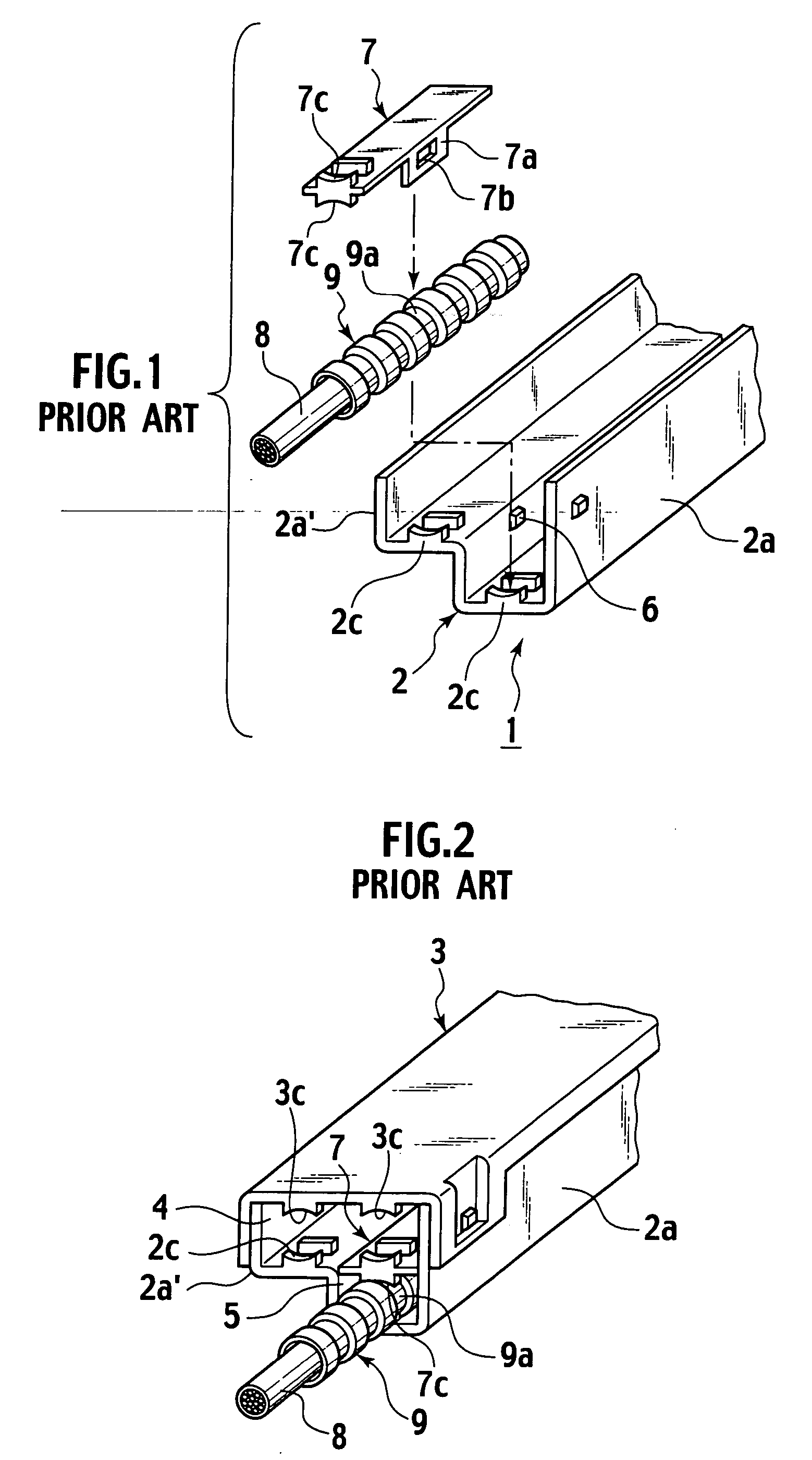
For this reason, attachment operation of the spacer 7 becomes complicated and wiring of the wire harness 8 in multi tiers of piling and arranging the wire harness 8 covered with the corrugate tube 9 within the protector main body 2 requires a lot of time.

Method used


Image

  • Wire harness protector
  • Wire harness protector
  • Wire harness protector

Examples


Embodiment Construction

[0025] There will be detailed below the preferred embodiments of the present invention with reference to the accompanying drawings. Like members are designated by like reference characters.

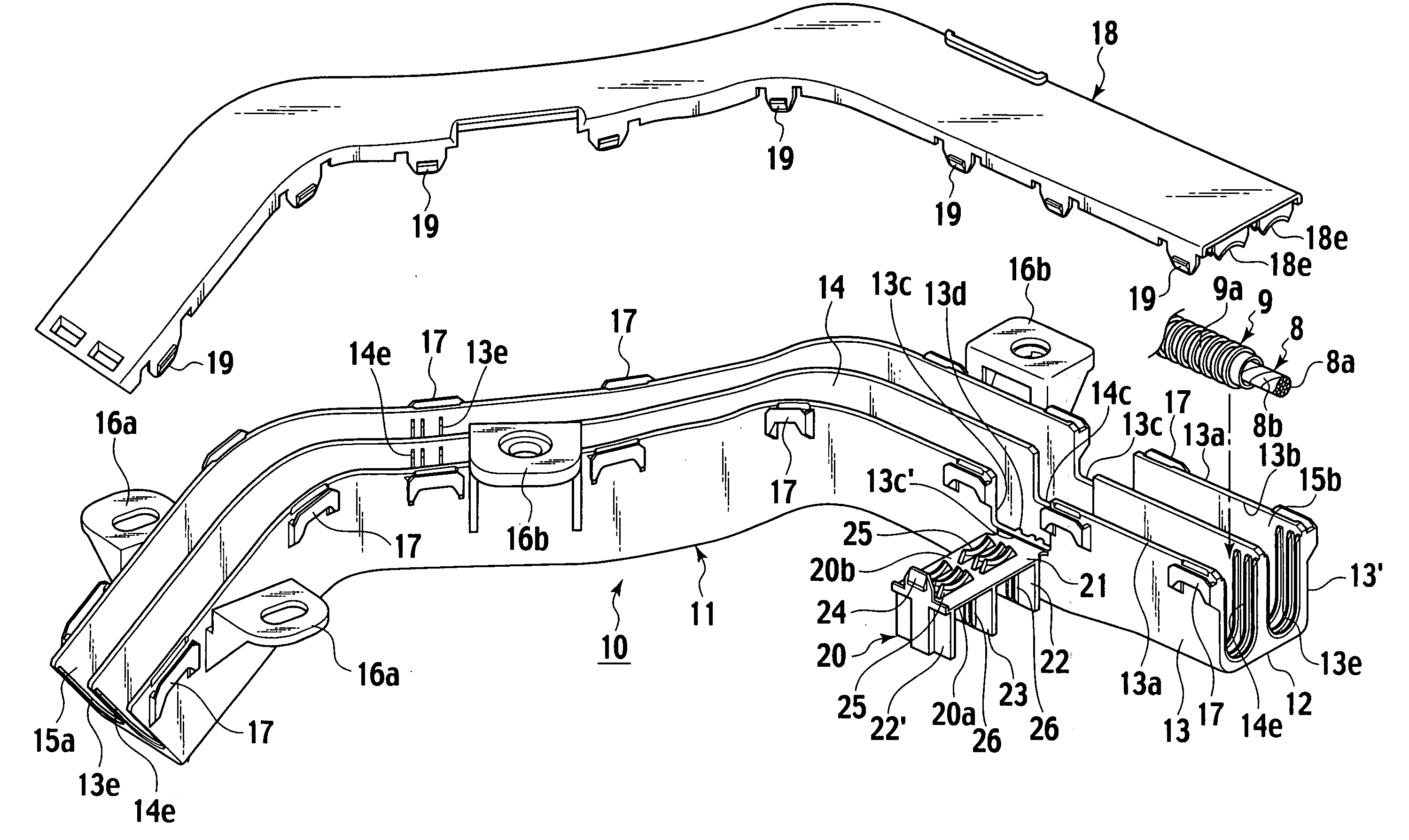
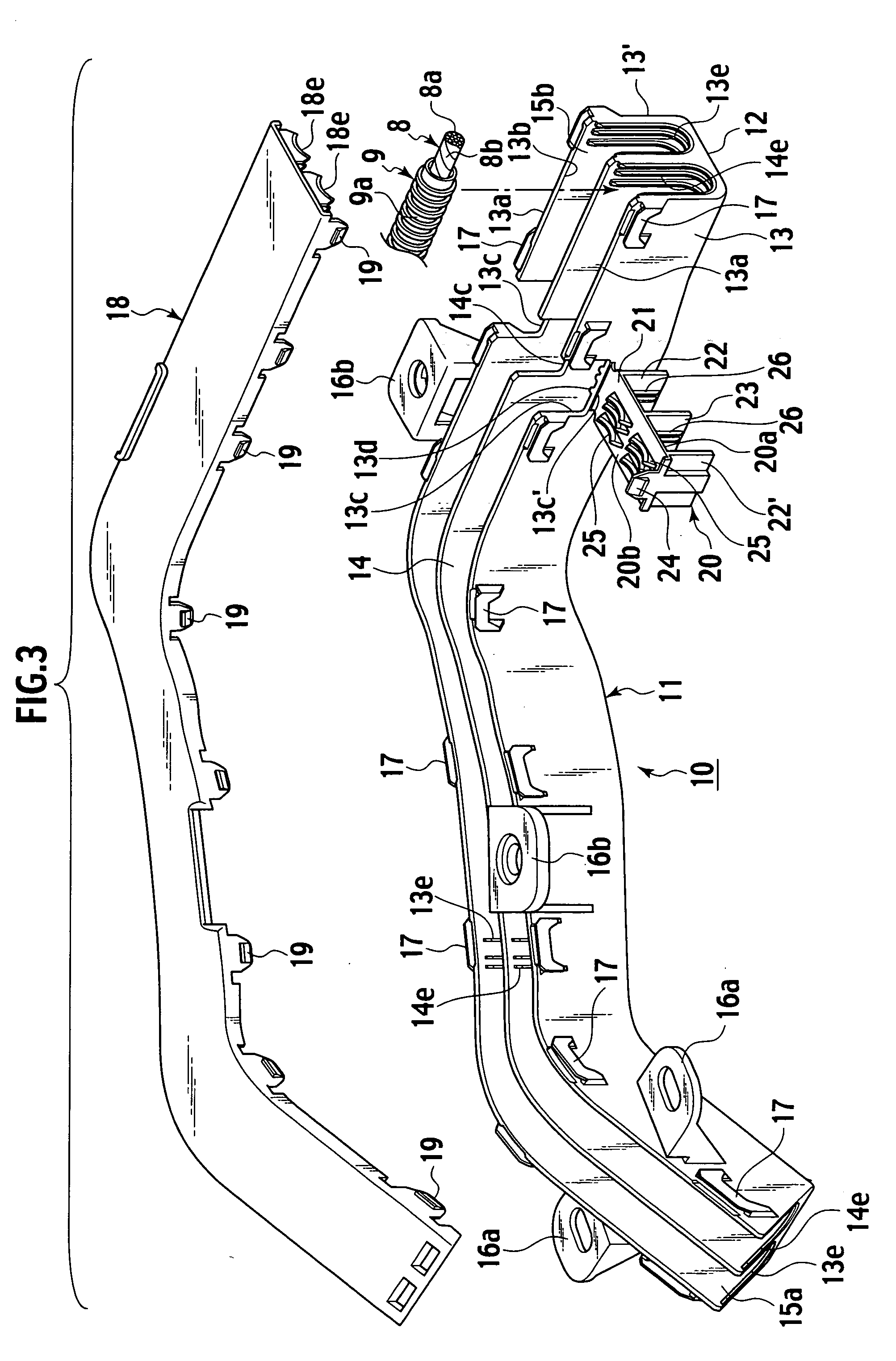
[0026]FIG. 3 is a perspective view showing the state where a cover of a wire harness protector of and embodiment according to the present invention is not closed and FIG. 4a is front view showing the state where the cover is closed.

[0027] As shown in FIG. 3 and FIG. 4, a wire harness protector 10 is comprised protector main body 11 of synthetic resin, which is formed of a bottom wall 12 and both side walls 13, 13′ which rise upwards from both ends of the bottom wall 12 in the shape of a gutter (in the shape of the square bracket “]” in cross section), the protector main body 11 accommodating corrugated tubes, into which a wire harness is inserted, so as to be piled in two tiers (multi tiers) in the vertical direction as well as to be placed in parallel in two rows in the horizontal direction via...


PUM


Abstract

In a wire harness protector comprised of a gutter-like protector main body with a bottom wall and both side walls, for accommodating corrugated tubes 9, into which a wire harness is inserted, in multi tiers in the vertical direction and a cover for covering an opening between upper ends of the both side walls of the protector main body, a wire holding spacer for positioning and holding the corrugate tube located in a lower tier within the protector main body, the wire holding spacer is formed integrally with one side wall of the both side walls of the protector main body through a hinge portion, and at position opposed to the other side wall of the both side walls of the wire holding spacer, a locking portion for engaging / releasing with / from an engaging portion of the other side wall is formed.

Description

BACKGROUND OF THE INVENTION [0001] 1. Field of the Invention [0002] The present invention relates to a wire harness protector for accommodating and protecting a plurality of wire harnesses for vehicles, for example. [0003] 2. Description of the Related Art [0004] Conventional type of wire harness protector is disclosed in patent brochures, Japanese Patent Applications Laid-Open No. 2001-359217 and Laid-Open No. 2002-225648. [0005] The conventional wire harness protector 1 (shown in FIG. 1 and FIG. 2) is comprised of a gutter-like protector main body 2 of synthetic resin for accommodating a corrugated tube 9, into which a wire harness 8 is inserted, and a cover 3 for covering both side walls 2a, 2a′ of the protector main body 2. [0006] An upper tier between the both side walls 2a, 2a′ of the protector main body 2 constitutes an upper tier accommodating portion 4 for accommodating two corrugated tubes 9, 9 and a lower tier constitutes a lower tier accommodating portion 5 for accommoda...

Claims


Application Information

Patent Timeline
IPC IPC(8): H02G1/00B60R16/02H02G3/04
CPCH02G3/0487H02G3/0418B60R16/0215
Inventor ARAI, HIROAKIOKAMOTO, AKIO
Owner YAZAKI CORP
Learn More