Fluid filter mounting apparatus and method

a technology for mounting brackets and filters, applied in chemistry apparatus and processes, separation processes, filtration separation, etc., can solve the problem that filters cannot be replaced within the cartridge housing, and achieve the effect of simple twisting motion

Inactive Publication Date: 2005-10-06
KNOLL GEORGE
View PDF32 Cites 17 Cited by
  • Summary
  • Abstract
  • Description
  • Claims
  • Application Information

AI Technical Summary

Benefits of technology

[0016] The cartridge also includes a closure member. The closure member is integrally formed with the filter housing. The housing, in some aspects of the present invention, may be tapered, to ease proper installation.
[0019] Each level of the closure member also includes at least one boss or tab. This boss or tab has at least one ramped face in the depicted embodiments. The bosses are fabricated and oriented to engage the inlet and outlet stop projections when the cartridge is installed in the manifold seat. The bosses are further fabricated and oriented in relation to one another so that upon installation, the outlet stop is engaged to open first and the inlet stop is engaged to open last. Thus, on installation, the outlet valve is already open when the inlet valve is opened, avoiding pressure shocks to the filter alignment and avoiding leakage. The order is reversed when the cartridge is being removed. The bosses close the fluid intake stop valve first, and close the fluid outlet stop second, also suppressing leakage and discontinuous pressure transitions.
[0021] Separately from the stop valve actuation bosses, the closure member and manifold further have ramped lugs dimensioned to cooperate with each other. These mounting lugs thread together to provide for a 90° turn screw fit. The inlet ports, stop valve bosses and mounting lugs are oriented symmetrically, so that a simple twisting motion will mount the cartridge in the manifold. Another boss and detent on the ramped lugs provide a positive stop, imparting a desirable “snap” sensation to a user, confirming proper installation.

Problems solved by technology

The alternative design not having a removable base, the cartridge may be removed and replaced from the manifold of the filter system, but the filter may not be replaced within the cartridge housing.

Method used


Image

  • Fluid filter mounting apparatus and method
  • Fluid filter mounting apparatus and method
  • Fluid filter mounting apparatus and method

Examples


embodiment

Locking Embodiment

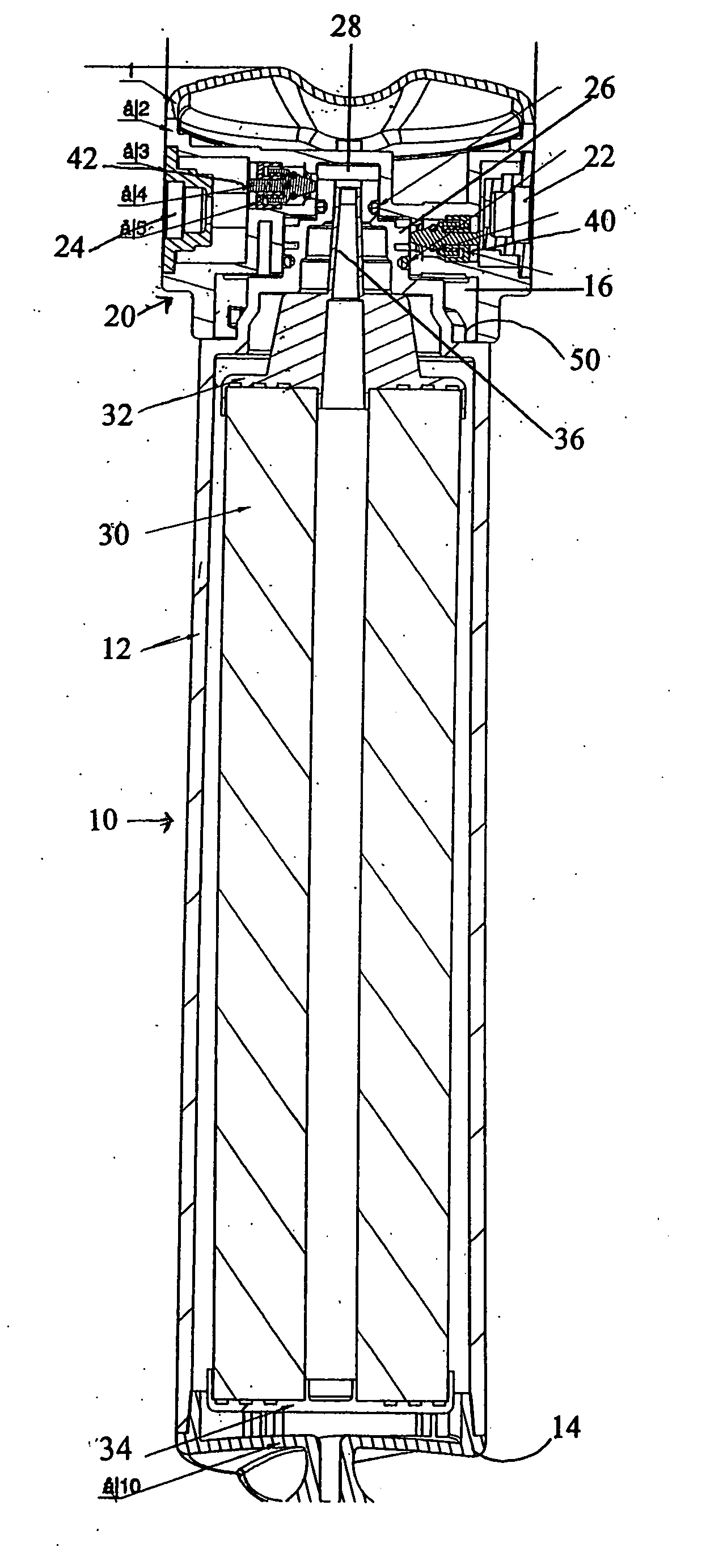
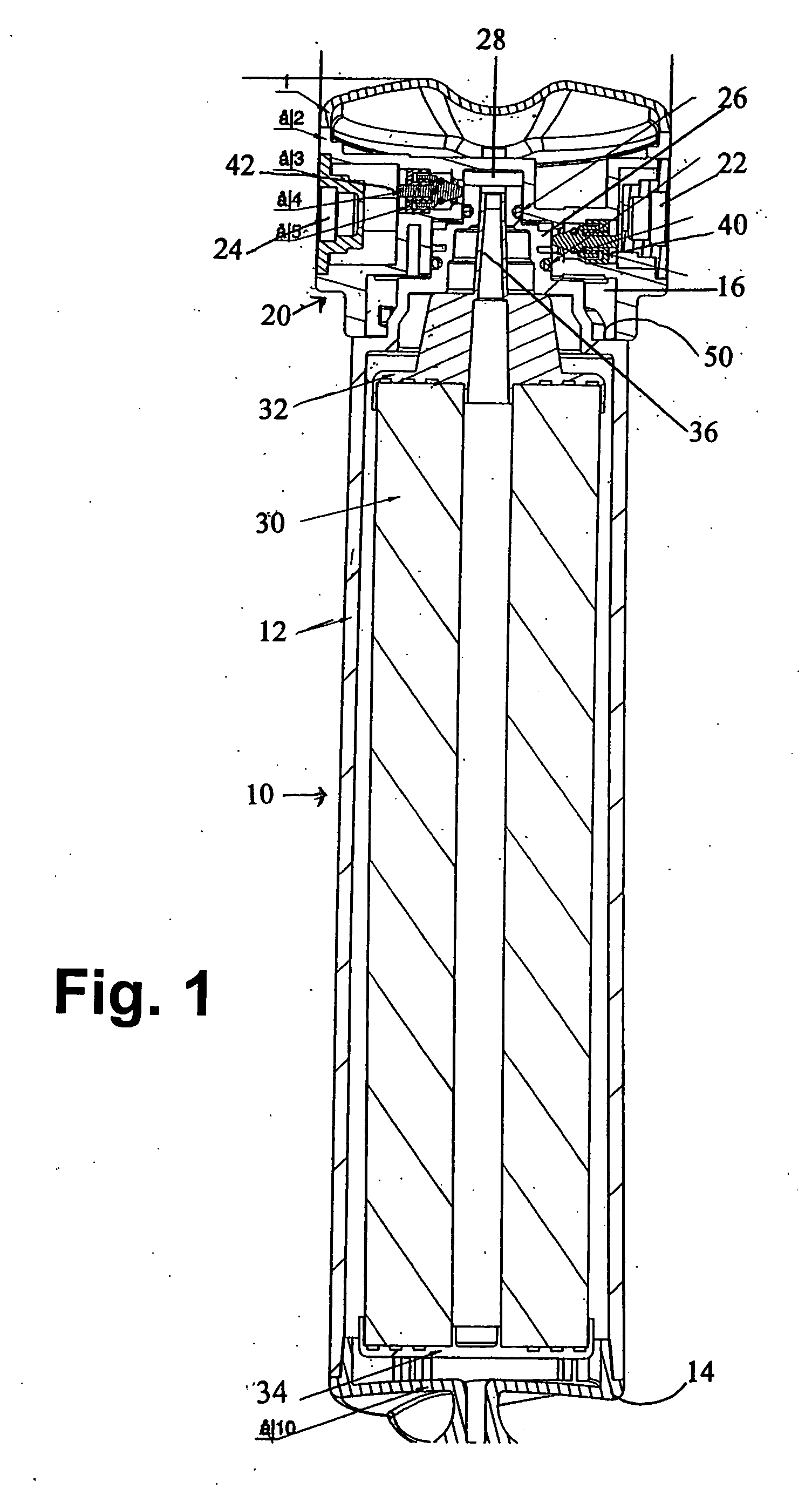
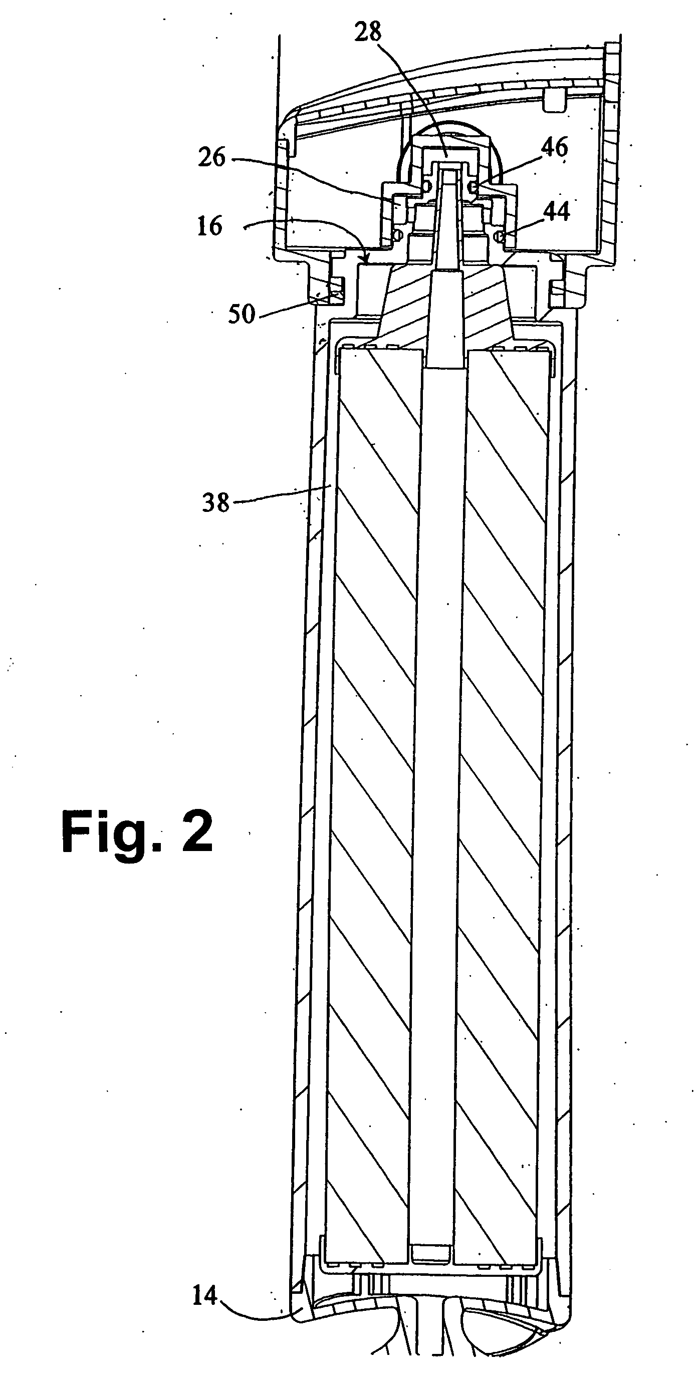
[0069]FIGS. 24 through 27 disclose locking alternative embodiments of the mounting bracket of the present invention. FIG. 24 is a perspective view of the mounting bracket including a lock 202. Internal to the bracket is a lock latch (not shown) engageable with a lock catch (not shown) within the bracket in order to lock it closed. FIGS. 25 and 26 show a mounting bracket having a cap formed to cover the base ends of the filter cartridge housings. The end cap also includes a lock 202. FIG. 27 discloses an alternative type of end cap, also covering the base ends of the cartridge housings and also having a lock 202.

[0070] In view of the foregoing, it will be seen that the several advantages of the invention are achieved and attained.


PUM

PropertyMeasurementUnit
outer dimensionaaaaaaaaaa
dimensionaaaaaaaaaa
outer diameteraaaaaaaaaa

Abstract

A fluid filter mounting apparatus includes a mounting bracket having a fluid intake and a fluid output, a first manifold and second manifold within the mounting bracket, each of the first manifold and the manifold having a fluid inlet and a fluid outlet. The fluid intake of the mounting bracket is in fluid communication with the fluid inlet of the first manifold. The fluid outlet of the first manifold is in fluid communication with the fluid inlet in the second manifold and the fluid outlet of the second manifold is in of fluid communication with the fluid output of the mounting bracket. A first mounting throughhole and a second mounting throughhole in the bracket are each dimensioned to align a first cartridge housing and a second cartridge housing with each of the first and second manifolds. Each of the throughholes are also dimensioned to secure a first portion of the filter cartridge housing when a closure member of the filter cartridge housing is seated in the manifold.

Description

CROSS-REFERENCE TO RELATED APPLICATIONS [0001] None. STATEMENT REGARDING FEDERALLY SPONSORED RESEARCH OR DEVELOPMENT [0002] Not Applicable. BACKGROUND OF THE INVENTION [0003] 1. Field of the Invention [0004] The present invention is a fluid filter cartridge mounting bracket with manifolds and a method for their assembly and for replacing cartridges. [0005] 2. Related Art [0006] Fluid filters, particularly water filters, are known. Drinking water filters adapted for use with plumbing in buildings where people work or live is common in many areas. A variety of filter types can be used, including charcoal, other granular types of filters or pleated membranes and the like. After any filter has been used for a period of time, it becomes less effective as impurities build up within it. Accordingly, filter systems need to provide for filter replacement. [0007] U.S. Pat. No. 5,336,406 to Stanford et al. is typical of a prior art filter system having a replaceable cartridge. One problem addr...

Claims


Application Information

Patent Timeline
Patent Type & Authority Applications(United States)
IPC IPC(8): B01D27/00B01D35/14B01D35/30
CPCB01D35/306B01D35/14
Inventor KNOLL, GEORGE
Owner KNOLL GEORGE
Why Eureka
Try Eureka