
Alignment and support apparatus

a technology of supporting apparatus and supporting rod, which is applied in the direction of mechanical equipment, machine supports, other domestic objects, etc., can solve the problems of water pressure problems, poor pipe work configuration, and permanent crooked plumbing configuration

Inactive Publication Date: 2005-10-06
DOVERSPIKE MARK
View PDF15 Cites 16 Cited by
  • Summary
  • Abstract
  • Description
  • Claims
  • Application Information

AI Technical Summary

Benefits of technology

"The invention is a device that helps keep pipes or conduits aligned correctly during a concrete pour. It has two attachment points for holding the pipe or conduit, and a bracket to attach it to a form board. This makes it easier to keep the pipe in place, especially when it's under pressure from the concrete. The device can be easily assembled by construction workers in the field and is dependable and effective. Its technical effects include improved alignment and support for pipes or conduits during concrete pour operations."

Problems solved by technology

Because the rebar and tape are typically removed prior to the pouring of concrete so that footers may be dug, the pipe or pipes will often sag prior to the concrete pour operation, and unless repositioned will result in a plumbing configuration that is permanently crooked when later embedded in cured concrete.
Often this sagging results in poor pipe work configuration that causes pipe leaks, water pressure problems, and drainage issues all of which are best avoided by maintaining proper support and alignment of pipe work and the like both prior to and during a concrete pour operation.
Thus, the '887 system is not suitable for preventing misalignment that can occur when concrete his poured into a form containing pipe work.
The '619 pipe support element is unsuitable for keeping a pipe aligned correctly during a concrete pour operation.
The '130 apparatus attaches to one point along a pipe's length making the '130 device unsuitable for maintaining pipe alignment during a concrete pour.
While the '880 device has a role to play in securing one or more water supply lines to a pipe, such as a drain or vent pipe, the '880 device is not sufficiently rigid to prevent pipe work moving out of alignment during a concrete pour operation.

Method used


Image

  • Alignment and support apparatus
  • Alignment and support apparatus
  • Alignment and support apparatus

Examples


first embodiment

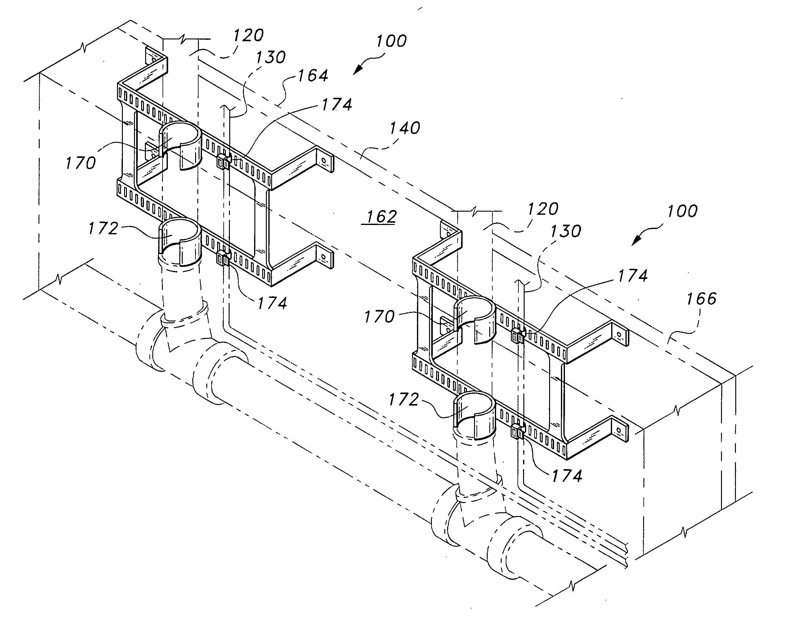
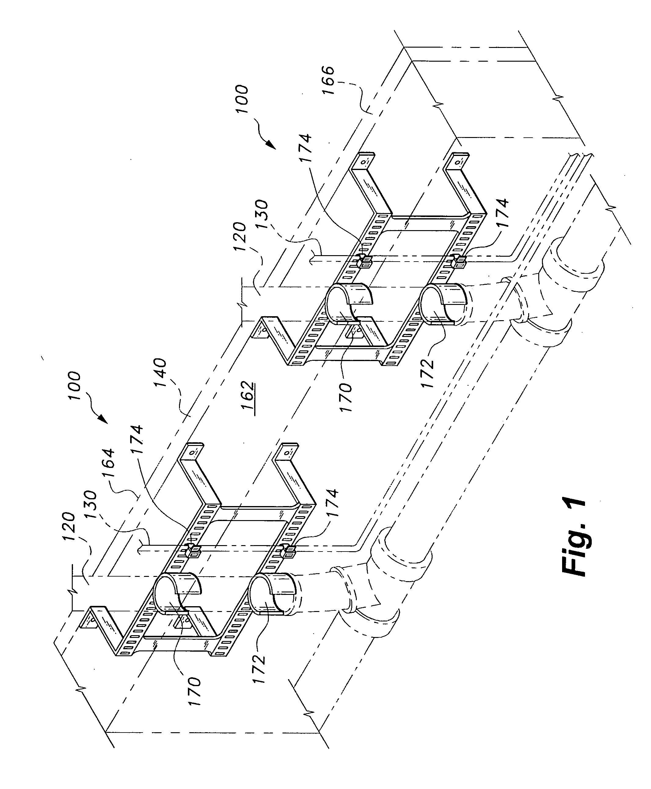
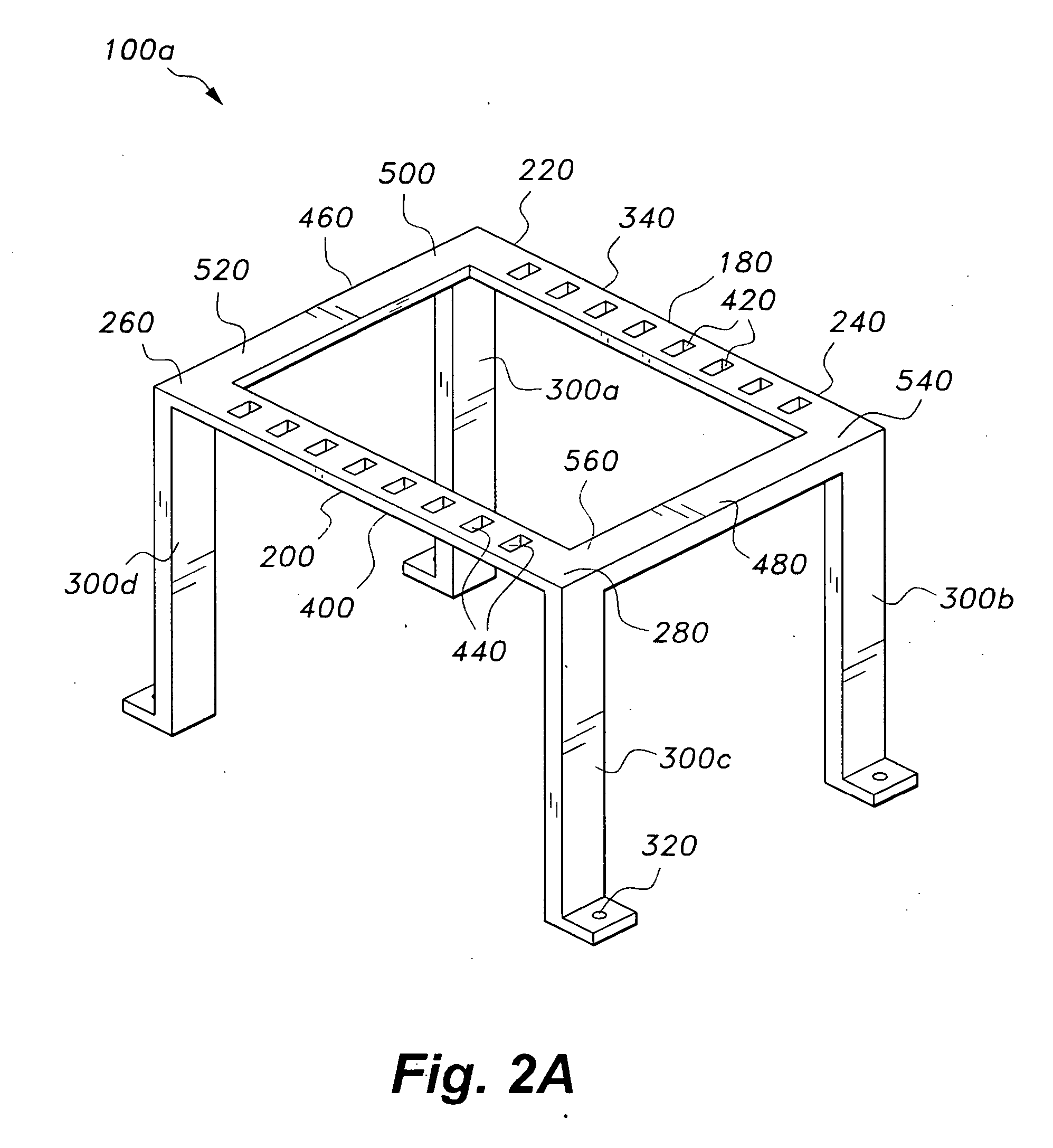
[0035]FIGS. 2A and 3A show the alignment and support apparatus 100 (respectively represented by the alpha-numeric labels 100a and 100b), according to the invention. The device 100 includes first 180 and second 200 elongated support members with opposed ends 220, 240, 260, and 280 as shown in FIG. 2A. Opposed ends 220 and 240 define a first middle portion 340, and opposed ends 260 and 280 define a second middle portion 400. The middle portions 340 and 400 respectively define a first plurality of apertures 420 and a second plurality of apertures 440. The terms “plurality of apertures” and “array of apertures” are herein regarded as equivalent terms.

[0036] Still referring to FIGS. 2A and 3A, first 180 and second 200 support members are connected to each other by means of first 460 and second 480 elongated alignment members. Specifically, first elongated alignment member 460 has opposed ends 500 and 520 that are respectively connected to support members 180 and 200, and second elongated...

second embodiment

[0039]FIGS. 2B and 3B show the alignment and support apparatus 100 (respectively represented by the alpha-numeric label 100c and 100d). In this embodiment the first 340 and second 400 middle portions respectively comprise first 600 and second 620 outward facing pipe brackets. The pipe brackets 600 and 620 are aligned with respect to each other to attach a pipe 120 at two positions along the pipe's length. The pipe brackets 600 and 620 may be in the form of a snap-in wherein a pipe 120 is snapped into the brackets 600 and 620 thus providing two separate grip points such that a pipe 120 cannot easily swivel about either bracket 600 and 620. This is an important improvement over the known prior art where a single pipe grip point is not sufficient to prevent swiveling of an affixed pipe during a concrete pour operation. It will be understood that the position and number of 600 and second 620 outward facing pipe brackets may vary.

third embodiment

[0040]FIGS. 4A and 4B show the invention wherein the alignment and support apparatus 100 (represented by the alpha-numeric label 100e) is made up of attachable components, i.e., the apparatus 100e is a kit. Thus, a construction worker using commonly available tools, such as an adjustable wrench, can assemble the kit 100e from the set of components shown in FIGS. 4A and 4B. Specifically, the support members 180 and 200 and alignment members 460 and 480 are shown bolted together using bolts 780 and complementary nuts 800. In this embodiment of the invention, the alignment members 460 and 480 define a plurality of corresponding connecting apertures 820a and 820b, respectively. Thus, selecting specific apertures 820a and 820b to bolt through can vary the distance between support members 180 and 200.

[0041] Still referring to FIGS. 4A and 4B, middle portions 340 and 400 respectively include at least one recessed inward curved surface 840 and 860 dimensioned to accommodate a section of a p...


PUM


Abstract

An alignment and support device for supporting and maintaining correct alignment of at least one pipe or conduit inside a form board during a concrete pour operation, the device comprising at least two attachment points for holding a pipe or conduit, and at least one attachment bracket, wherein the at least one attachment bracket is capable of attaching the alignment and support device to a form board.

Description

CROSS-REFERENCE TO RELATED APPLICATIONS [0001] Not Applicable. STATEMENT REGARDING FEDERALLY SPONSORED RESEARCH OR DEVELOPMENT [0002] Not Applicable. BACKGROUND OF THE INVENTION [0003] This invention relates to an alignment and support apparatus for aligning and supporting pipes and the like during a concrete pour operation. More specifically, this invention relates to an apparatus that keeps pipes and the like correctly aligned with respect to a form board during a concrete pour operation. [0004] Many building structures, such as foundations, floors, ceilings, walls, and the like, include a concrete slab having pipes and the like embedded therein. Form boards are typically used to provide the desired shape of concrete slab. The form boards are usually made out of wood, with pipe work and the like supported therein. Concrete is poured into the form, and once set, the form is removed to reveal a concrete slab with pipes and the like embedded therein. It is very important that the pip...

Claims


Application Information

Patent Timeline
Patent Type & Authority Applications(United States)
IPC IPC(8): E02B7/14E02D11/00F16L1/09F16L1/10F16L3/08F16L3/10F16L3/12
CPCF16L1/10F16L1/09
Inventor DOVERSPIKE, MARK
Owner DOVERSPIKE MARK
Learn More