Evidence collection holder for sample automation

a technology for storing and collecting samples, applied in the field of storing samples for sample automation, can solve the problems of inability to properly collect samples, lack of visual characteristics, and inability to cooperate with people,

Inactive Publication Date: 2005-10-06
BODE TECH GROUP
View PDF5 Cites 42 Cited by
  • Summary
  • Abstract
  • Description
  • Claims
  • Application Information

AI Technical Summary

Problems solved by technology

In the collection of biological specimens, it is necessary to associate information about the subject with the specimen at the time of collection as there is no manner for identifying a biological specimen by simple inspection.
A particular issue in the collection of the biological sample is that the sample collection is often taken from a living, uncooperative person.
Once the specimen is on the absorbent, the handle is no longer needed, a present complicating factor in specimen storage and analysis due to the extra bulk and size.
This lack of visual characteristics foils any attempt to properly identify such a biological fluid or cellular sample once it has become separated from its identifying information.
Another problem or issue presented in the analysis of biological specimens is the need to extract or transfer the collected sample from the original collection absorbent and onto an alternate medium to permit analysis or testing of the specimen using the analysis equipment that is available in the selected laboratory.
This separation of specimen from identifying information can lead to mistakes in associating the specimen with the correct subject or suspect or can lead to the “chain of custody” being open to question in court and a failure of proof of a crime.
Sample misidentification is a major source of error both in laboratory analysis and in substantiating criminal evidence.
An additional issue associated with the collection of the biological sample is the need to test or analyze the sample for comparison purposes with other specimens.
For example, in automatic sample testing devices originally designed for the insurance testing industry, the standards of assuring the association of a specimen with its identifying information is not as rigorous as is required for evidence “chain of custody.”

Method used


Image

  • Evidence collection holder for sample automation
  • Evidence collection holder for sample automation
  • Evidence collection holder for sample automation

Examples


embodiment 10

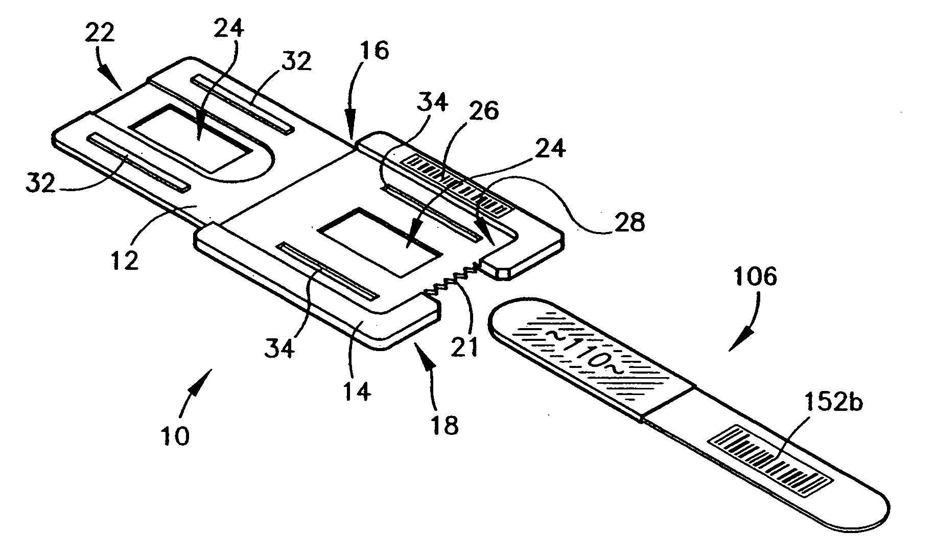
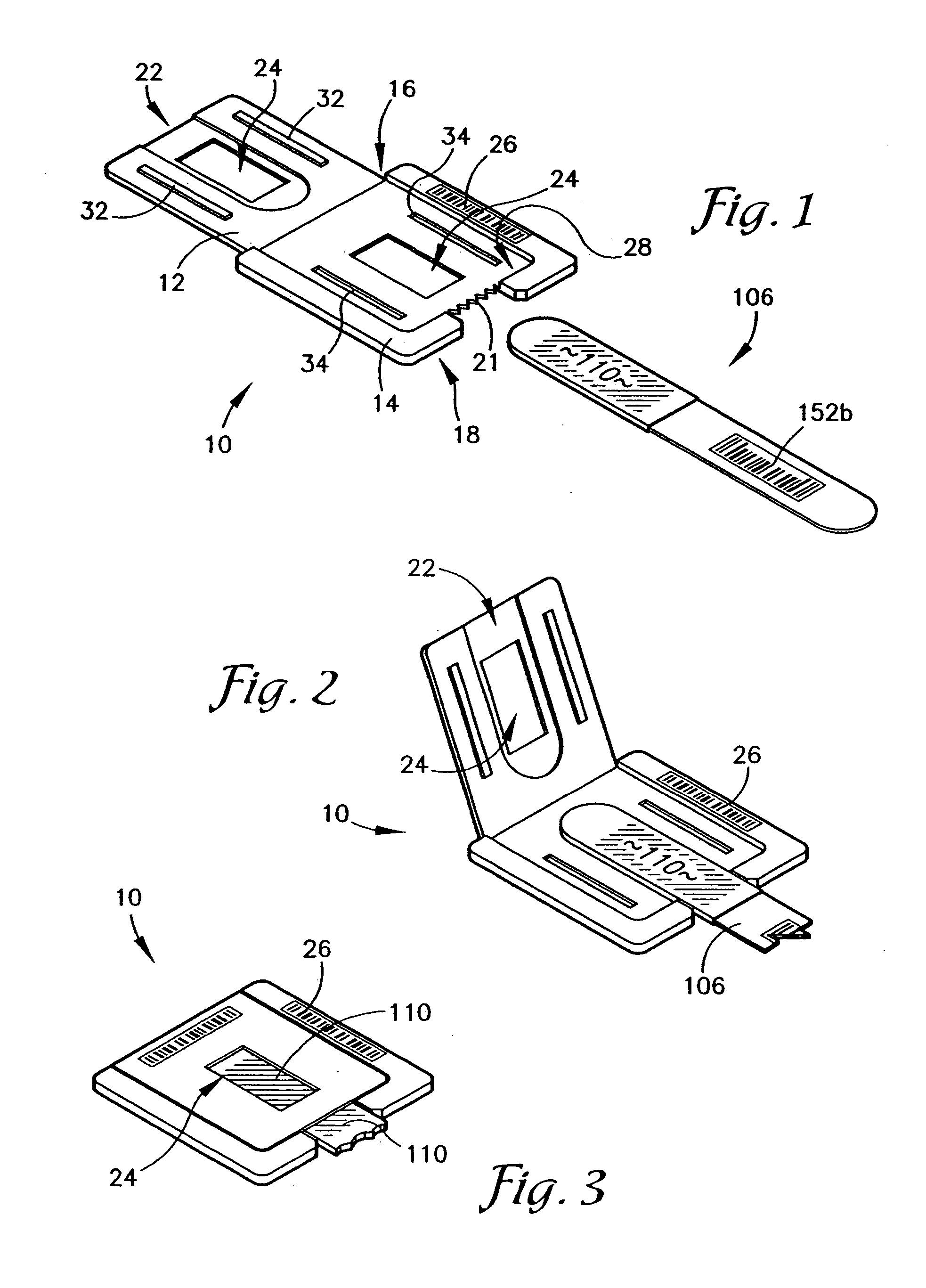
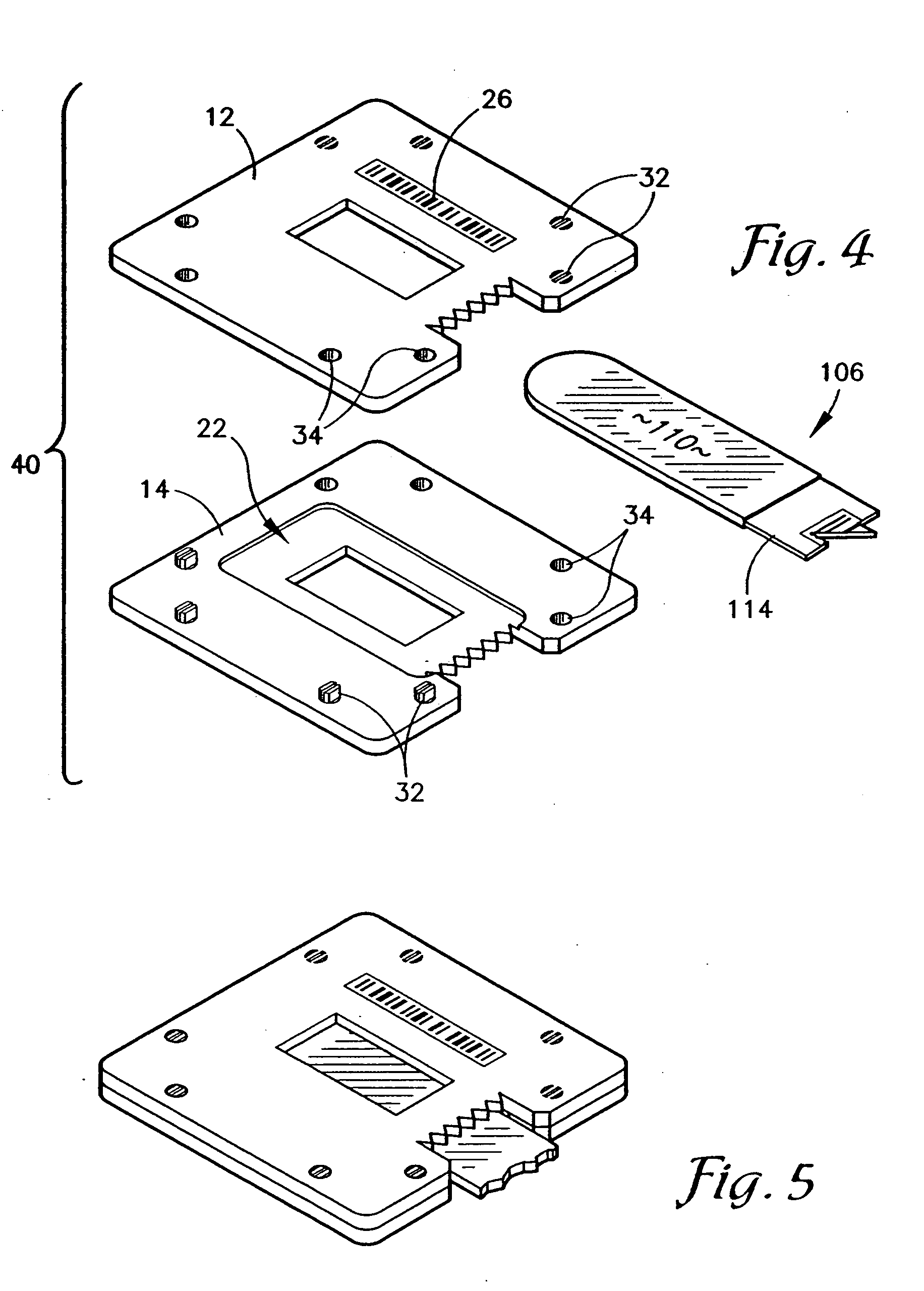
[0052] Referring now to FIGS. 1-3, a sample carriage device embodiment 10 is shown which allows the paper absorbent 110 of the specimen / sample collector 106 to be inserted into the carriage device 10 and the paper absorbent 110 captured within the carriage device and the paper separated from the collector handle 114 (FIG. 10) by serrated edges 21 on device 10.

[0053] Referring to FIG. 1, embodiment 10 is comprised of an upper portion 12 that is connected to a bottom portion 14 by the use of a hinge means or staple connection or fold along back edge 16 to permit top portion 12 to be separable from bottom portion 14 along front edge 18. Front edge 18 includes cutter portion 21 having teeth-like edges or serrations in front edge 18 the purpose of which shall be described hereinafter.

[0054] In operation, a specimen or sample collector 106 such as the one shown in FIGS. 8-10 can be used with any of the embodiments of FIGS. 1-7. Other configurations or shapes of absorbents 110 may be used...

embodiment 50

[0061] In operation, the function of the embodiment 50 of FIGS. 6 & 7 is as follows: A handle sample holder 106 having a bar code 152b and having a collection absorbent or paper 110 attached thereto such as the collection device 106 of FIGS. 8-10 of the present application is inserted into bottom portion or half 14 of device 50. As is shown in FIG. 6, windows 52a, b and 54a, b are included on both top portion 12 and bottom portion 14 of holder 50. A support band 56 bridges windows 52a, b and 54a, b. Support band 56 supports device 106 within the holder 50 while allowing the bar code 152b on device 106 to be viewed and read with a bar code scanner and sample collection portion 110 of device 106 to be exposed and accessible and viewable at all times.

[0062] It will be appreciated that during manufacture, bottom portion 12 and top portion 14 of device 50 can be constructed so the top and bottom portions are identical. Thus, the individual inserting device 106 into the halves of the devi...

embodiment 100

[0070] In FIG. 15, the reverse side of embodiment 100 is shown, including the reverse side 190 of information portion 175 and the reverse side 200 of holder portion 150. On the reverse side of the information portion, areas for marking the date the card 100 was received at various locations 194 is provided, a space for a department of justice specimen number 164, identification and signature of the collecting agent 196, the name and signature of the subject 198, and space for a second fingerprint 192. The second fingerprint can further serve as a correlating marking proving that the individual whose biological sample and / or finger print appeared in holder 150 also was available to provide the finger or thumb print which was placed on the reverse side 190 of information portion 175.

[0071] Referring now to FIGS. 16 and 17 alternative embodiments 200, 200a are presented. In the embodiment of FIG. 16, a perforation line 158 is shown in the location described in the discussion of the emb...


PUM

PropertyMeasurementUnit
adhesiveaaaaaaaaaa
areaaaaaaaaaaa
sizeaaaaaaaaaa

Abstract

A device and method of securing the original biological specimen collection absorbent within a holder to permit use of the absorbent within automatic specimen analysis devices and to permit continuance of a chain of custody is provided.

Description

CONTINUATION DATA [0001] This application is a continuation-in-part application of application Ser. No. 10 / 020,257 filed Dec. 14, 2001. The specification of U.S. Pat. No. 6,440,087 is incorporated herein by reference. This application further claims priority to provisional patent application Ser. No. 60 / 567,081 filed Apr. 30, 2004, and provisional patent application Ser. No. 60 / 617,100 filed Oct. 7, 2004.FIELD OF THE INVENTION [0002] The field of the present invention is devices for collecting biological samples. In particular, the several embodiments of the present invention provide a device having an absorbent for collection of oral fluids or blood specimens or cells thereon. Several embodiments of the specimen collection devices provide for recordation of identifying information and for division of the sample into separate identifiable portions to permit use of the specimen as law enforcement evidence. Generally, the embodiments of the invention further provide a holder for conta...

Claims


Application Information

Patent Timeline
Patent Type & Authority Applications(United States)
IPC IPC(8): G01N1/02A61B10/02G01N1/00B01L9/00A61L2/08A61L2/20C12Q1/68B01L3/00A61L2/00A61B10/00A61B19/00
CPCA61B90/96B01L2300/021B01L2200/185B01L9/52B01L3/5055B01L2300/0825A61B10/02A61B10/0096A61B10/0064A61B10/0051B01L3/50273B01L2300/069B01L2200/141B01L3/508A61B10/00C12Q2527/125G01N2001/028G01N2001/007C12Q1/6806B01L2300/0887
Inventor SANGHA, JANGBIR S.
Owner BODE TECH GROUP
Why Eureka
Try Eureka