
Automatic injection device

a technology of injection device and injection chamber, which is applied in the direction of intravenous device, other medical devices, injection needles, etc., can solve the problems of difficult holding and orientation of existing injection devices at the injection site, particularly vigorous injection process, and inability to properly administer injection

Inactive Publication Date: 2005-10-06
PA2008
View PDF99 Cites 202 Cited by
  • Summary
  • Abstract
  • Description
  • Claims
  • Application Information

AI Technical Summary

Problems solved by technology

However, while existing products offer a convenient, self-contained and single-dose administration suitable for emergency uses, they have various drawbacks.
For example, the injection process itself is particularly vigorous, maybe even violent due to both actuation force and high puncture force.
Furthermore, the existing injection devices are difficult to hold and orient at the injection site.
The combination of the vigorous actuation and difficult handling sometimes makes a proper dosing difficult.
In any case, it detracts from the comfort level of the patient, the injection administrator or both.
Furthermore, because of the violent nature of the existing device, multiple injections are particularly undesirable.
If only one hand of a patient or other person is available for using the device, this further exacerbates the problem.
Thus, these devices require two-hand operation.
Furthermore, such existing devices can be difficult to actuate properly.
While it is certainly desirable to avoid inadvertent actuation, once it is desired, the prior art devices can sometimes make it difficult to complete.
In fact, it is often difficult to tell when the existing products are armed for injection.
Still further, it is sometimes difficult to determine that they are properly oriented, and not reversed.
An inadvertent reversal and firing of the device is extremely undesirable, and may be dangerous not only to a person administering the dosage, but also to the patient in need of it.
Furthermore, the proper actuation of the device may be difficult to ascertain with existing products, adding further to the uncertainty of proper dosing.
With existing devices, it is also difficult to determine whether the injection process occurred correctly and whether a proper or a full amount of the dosage of the API has been dispensed to the patient.
This presents difficulties if the needle encounters a greater resistance than normal.
In such a case, the needle may not penetrate properly into the skin and muscle at the injection site.
Second injections, as noted, are undesirable, and may not even be possible unless an additional device is available.
However, in emergency situations, time references and elapsed time are often skewed.
Furthermore, a parent or other person may be fighting with a reluctant child and will not have the ability to pay attention to a clock or watch during administration.
Therefore, there is often a great amount of uncertainty regarding when the process is complete when using existing products.
Existing products do not adequately address such issues.
In some devices, the needle remains exposed after usage, thereby presenting a hazard.
The EpiPen™, for example, requires the user to manipulate the needle after use, thus increasing the risk of needle stick wounds.
Also, they are often retractable, so that some sticking / pricking hazard still exists.
As may be appreciated, such drawbacks of existing devices are even more highlighted in emergency situations where little time is available for reading literature, orienting the device, or just generally figuring out how the device works, checking to see that the injection is complete, and disposing of the used device.

Method used


Image

  • Automatic injection device
  • Automatic injection device
  • Automatic injection device

Examples


Embodiment Construction

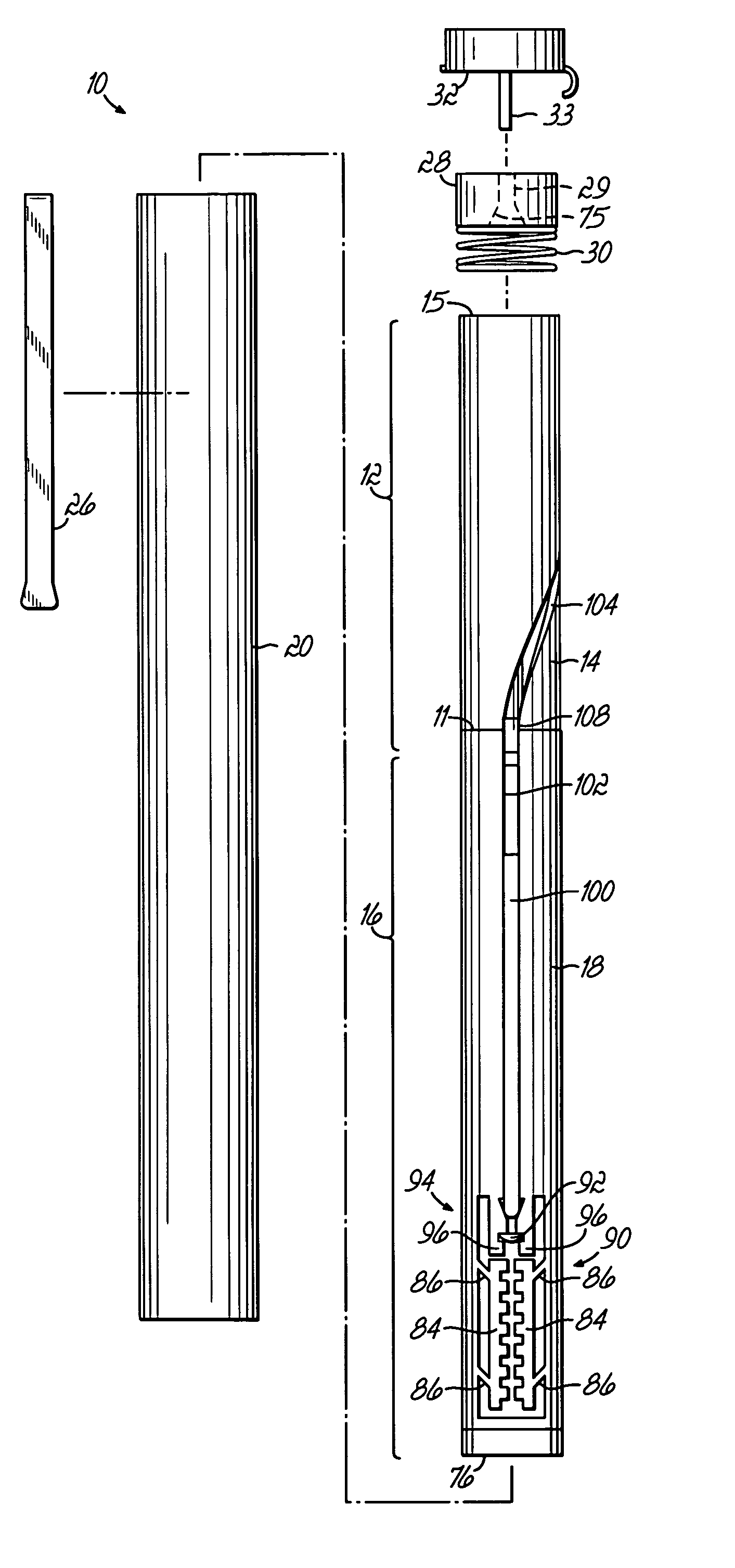
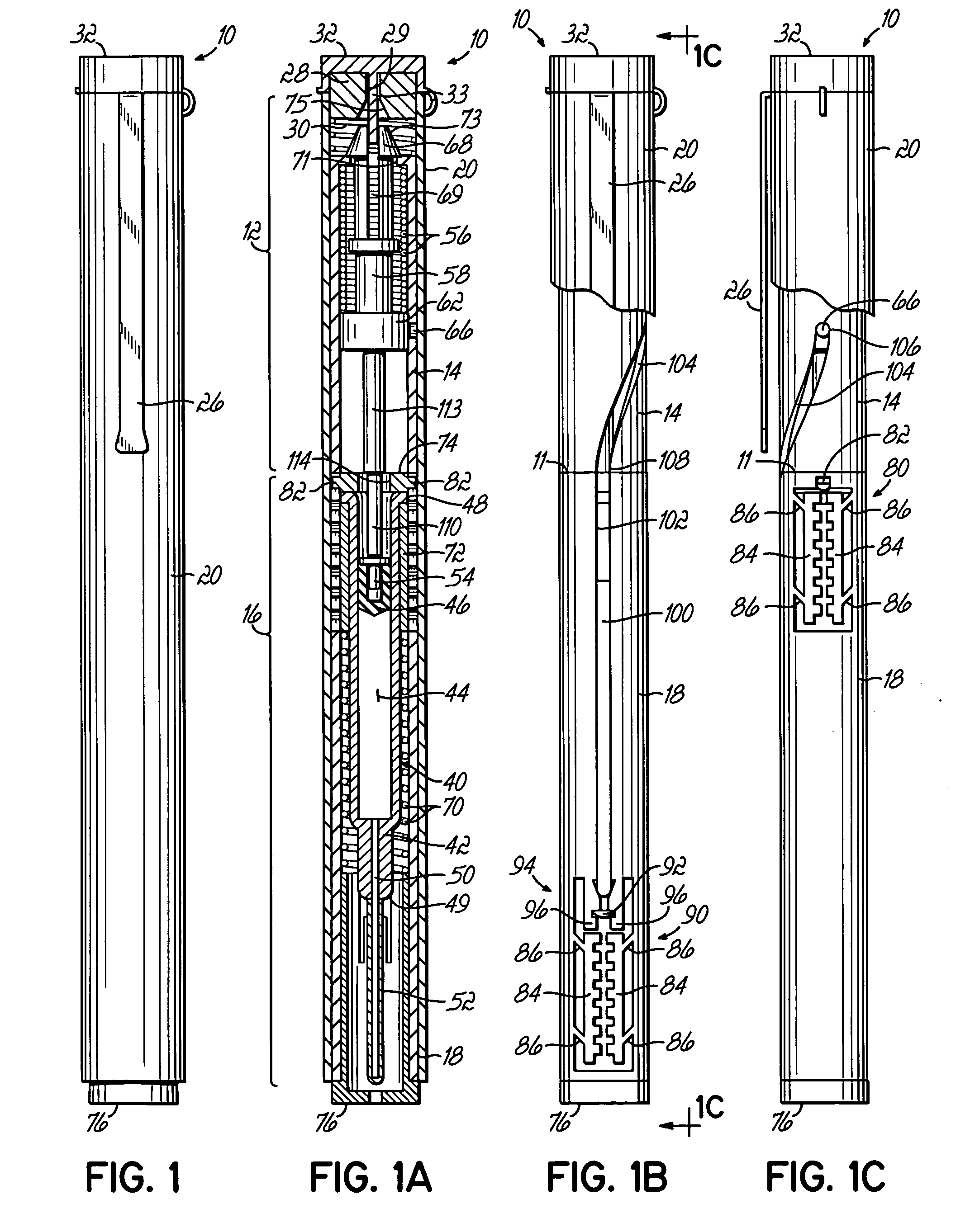
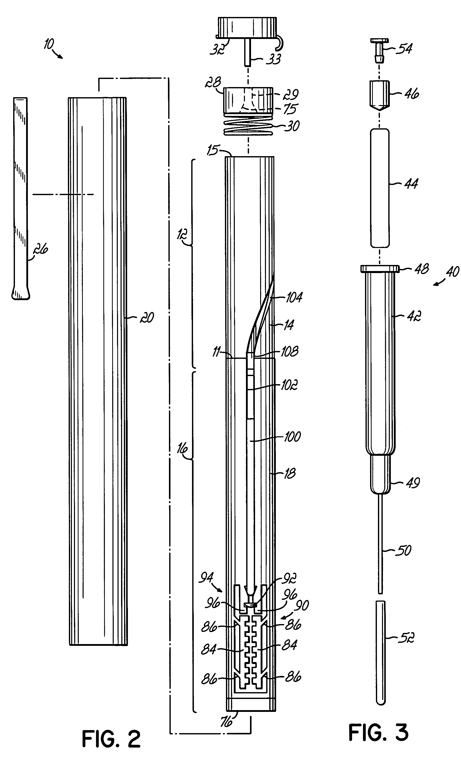
[0044]FIGS. 1-1C illustrate various views of one embodiment of an injector device incorporating various aspects of the present invention. In the embodiment illustrated in some of the Figures, the injector device has a general pen-like design, including an inner body or tube surrounded by an outer pen-shaped housing. Alternatively, other housings, as illustrated in FIGS. 6A-6C may be used. In the injector device 10, illustrated in the Figures, the inner body as shown in FIGS. 1B and 1C is divided into a plurality of body portions, primarily two sub-bodies, which house different subassemblies. The different sub-bodies contact or are coupled at line 11 and cooperate to act generally as a single body or body structure as described herein. Injector device 10 includes a drive subassembly 12, which includes the body portion or body 14, and an injector subassembly 16, which includes body or body portion 18. Although illustrated as individual bodies 14, 18, a unitary body structure for housi...


PUM


Abstract

An injector device comprising a body containing a syringe with a needle and plunger, a drive spring coupled with the syringe and operable, when released, to drive the syringe forward to inject the needle and subsequently to dispense a dosage from the syringe, a housing containing the body and drive spring, and a release apparatus coupled with the housing. The drive spring is initially locked in an unreleased position, and the body is slidable with respect to the housing and configured for sliding upward in the housing when the injector device is pressed down at an injection site to engage the release apparatus and release the drive spring for delivering a dosage.

Description

RELATED APPLICATIONS [0001] This application is a continuation-in-part application of U.S. patent application ser. No. ______, entitled “Automatic Injection Device” and filed Mar. 30, 2004, under US Post Office Express Mail No. EV026538066US, which is incorporated by reference herein in its entirety.FIELD OF THE INVENTION [0002] This invention relates generally to injection devices and specifically to automatic injection devices. BACKGROUND OF THE INVENTION [0003] In certain medical situations, including potentially life-threatening situations, it has been a recognized procedure to provide a rapid and timely injection of an active pharmaceutical ingredient (API) in order to address a specific condition or symptoms. For such situation, single use, automatic injection devices are available. Automatic injection devices are self-powered, such as by an internal drive system, and will automatically inject a needle and dispense of dosage of an API upon being actuated or “fired.” Usually, a...

Claims


Application Information

Patent Timeline
Patent Type & Authority Applications(United States)
IPC IPC(8): A61M5/00A61M5/20A61M5/31A61M5/32
CPCA61M5/2033A61M5/3129A61M5/326A61M5/3271A61M2005/2013A61M2005/206A61M2005/2073A61M2205/583A61M5/3157
Inventor GONZALES, GILBERT R.HUDDLESTON, MATTHEW J.HUGHES, KENNETH E.
Owner PA2008
Learn More