Grouping and displaying multiple tasks within an event object of an electronic calendar

a task and event object technology, applied in the field of grouping and displaying multiple tasks within an event object of an electronic calendar, can solve the problems of cumbersome workaround management for more than a small number of tasks, inability to allow the user to specify start and end times, and high program change costs,

Inactive Publication Date: 2005-10-06
CARY JAMES C
View PDF14 Cites 184 Cited by
  • Summary
  • Abstract
  • Description
  • Claims
  • Application Information

AI Technical Summary

Problems solved by technology

When dates are present, the systems often do not allow the user to specify start and end times, just dates.
Users do have the option of inputting task information in the form of an appointment or event object, thereby displaying a particular task as a time-bound graphical object in the user's calendar, but, this work-around is cumbersome to manage for more than a small number of tasks.
Set-up costs, maintenance costs, and program change costs are likely to be too high with simple template mechanisms to ensure a viable market for products of this type.

Method used


Image

  • Grouping and displaying multiple tasks within an event object of an electronic calendar
  • Grouping and displaying multiple tasks within an event object of an electronic calendar
  • Grouping and displaying multiple tasks within an event object of an electronic calendar

Examples


second embodiment

[0266] Description of Second Embodiment

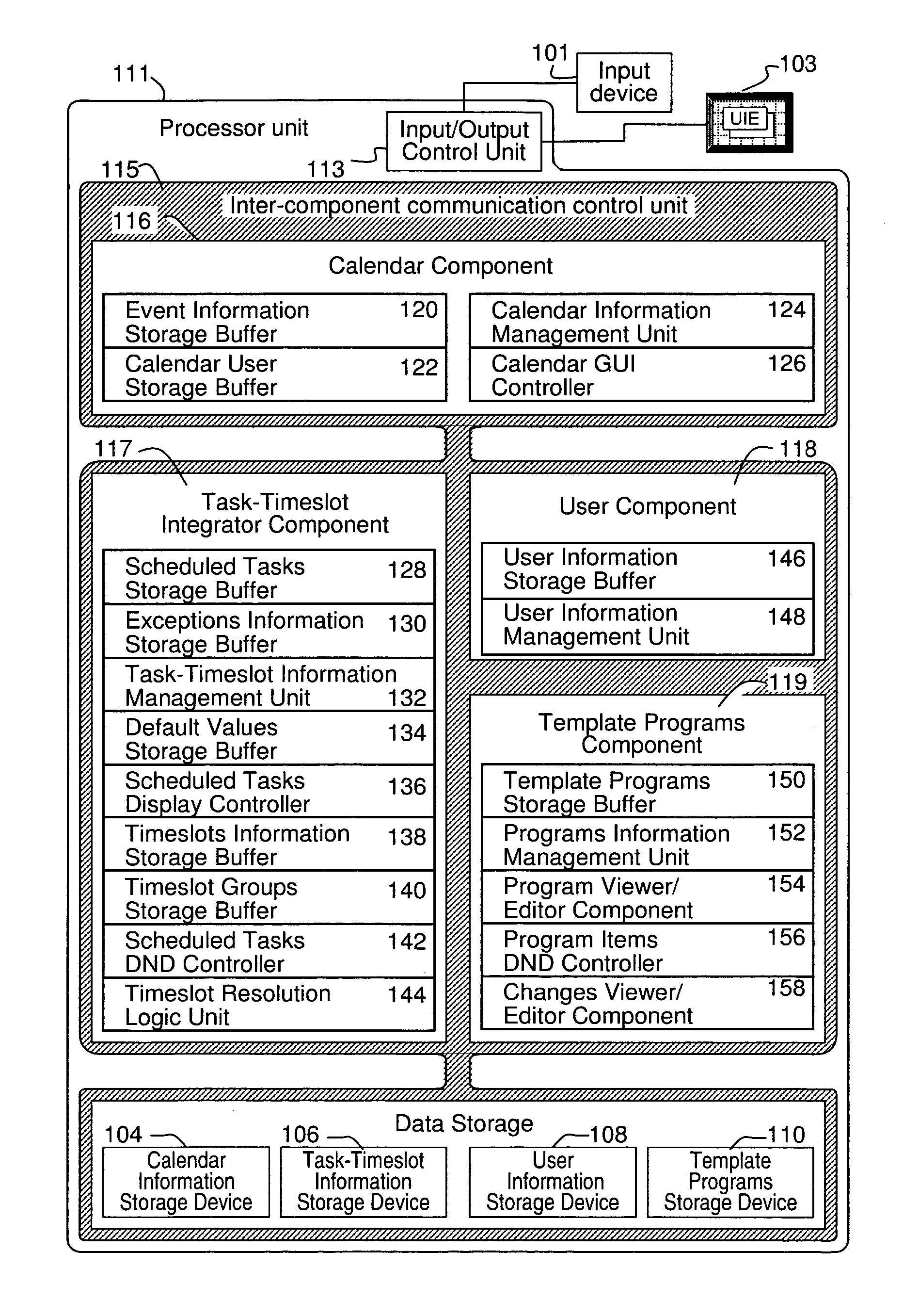
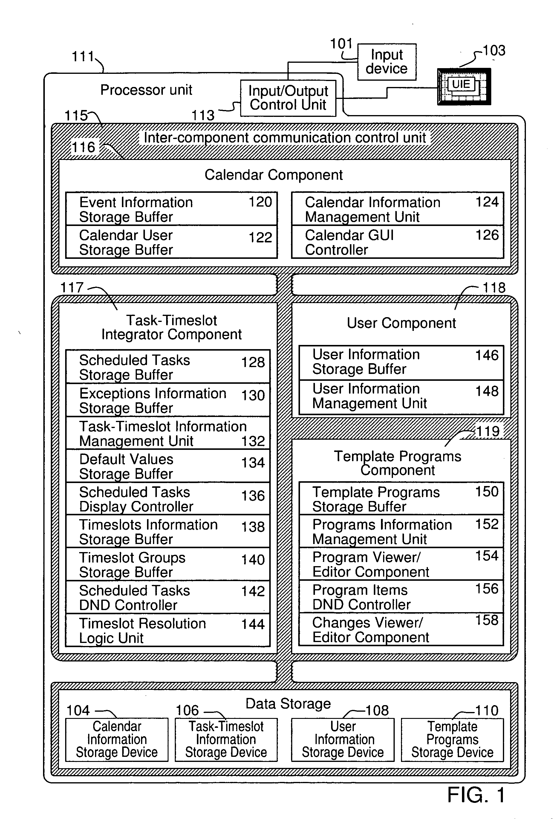
[0267]FIG. 25 is a diagram showing the configuration of a schedule management system according to a second embodiment of the invention wherein many of the structures represented in the preferred embodiment are integrated with structural elements of an electronic calendaring system. Under the second embodiment, the schedule management system includes the input device 101 such as a pointing device for inputting position information, the display unit 103, a calendar information storage device 1004, the user information storage device 108, a template programs storage device 1010, and the processor unit 111.

first embodiment

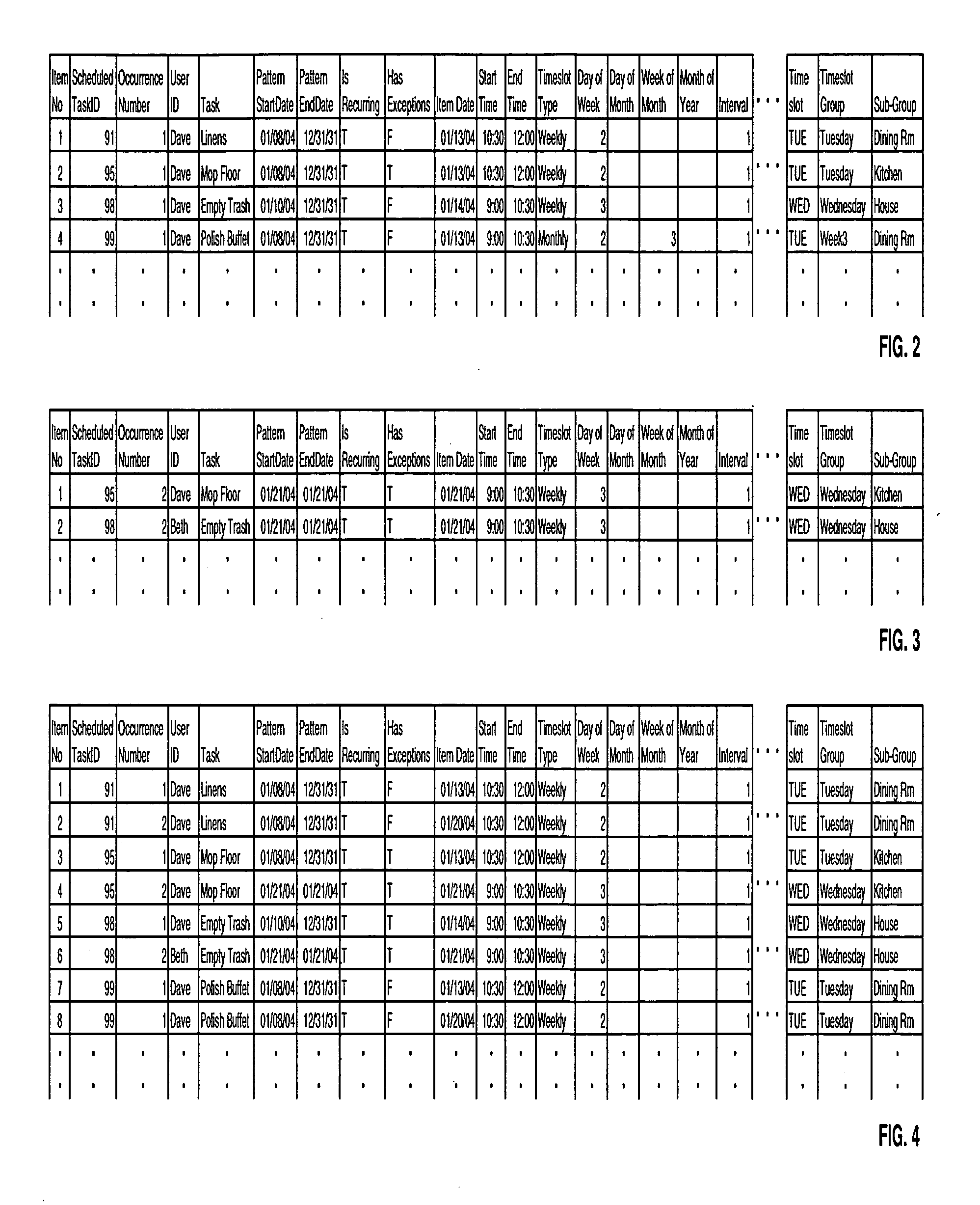
[0268] The calendar information storage device 1004 stores event information, exceptions information, and scheduled tasks information as shown in FIGS. 26, 27 and 28 respectively. From the event information, exceptions information, and scheduled tasks information as shown in FIGS. 26 to 28 it is possible to develop information equivalent to the scheduled tasks information under the first embodiment as shown in FIG. 9. The event information as shown in FIG. 26 provides a definition of a particular recurrence pattern for a period defined by the PatternStartDate and PatternEndDate fields. The values in the PatternStartDate and PatternEndDate fields of the event information as shown in FIG. 26 will be calculated as the earliest PatternStartDate value and the latest PatternEndDate value respectively among associated scheduled tasks information items. When the Boolean HasLinkedTask field holds a value of “True”, it indicates that the particular item of event information as shown in FIG. 2...


PUM


Abstract

A system for the display and editing of scheduled tasks and timeslots represented in the form of user interface elements embedded in the calendar regions of the graphical user interface of electronic calendaring systems. It provides structures and methods for editing schedule data in the form of individual tasks and timeslots, sub-groups of tasks and timeslots, and related collections of scheduled tasks and timeslots. It provides for the automated generation of scheduled tasks and timeslots information using a template structure, thereby reducing the amount of decisions and key strokes required for the user to generate and load into their personal calendars a predefined program of recurring tasks and timeslots. Methods are employed to minimize routine program maintenance requirements. In particular, a structure is provided which allows scheduled tasks information to be defined in such a way that particular tasks may be added or removed from a user's schedule either after predefined intervals of time, or, dynamically in response to changes in a predefined metric such as might be used to measure a user's skill level or efficiency.

Description

CROSS-REFERENCE TO RELATED APPLICATIONS [0001] This application claims the benefit of U.S. Provisional Application No. 60 / 560,439, filed Apr. 6, 2004.BACKGROUND OF THE INVENTION [0002] 1. Field of the Invention [0003] The present invention relates to the display, editing, and automated generation of scheduled tasks within an electronic calendaring system. [0004] 2. Description of Related Background Art [0005] Electronic calendaring systems have become a common and essential tool for organizing one's personal and business affairs. These systems enable users of all ages and occupations to quickly and easily monitor tasks and appointments, coordinate assignments and meetings with others, and, do so over a variety of computer systems and devices asynchronously and with little to no technical support. The newest of these systems encompass an array of related functions: to-do list functions, phone books, notes, journals, electronic mail, wireless communications, and, recently, integration...

Claims


Application Information

Patent Timeline
Patent Type & Authority Applications(United States)
IPC IPC(8): G06Q10/00G06F7/00
CPCG06Q10/109
Inventor CARY, JAMES C.
Owner CARY JAMES C
Why Eureka
Try Eureka