

Mount table, surface texture measuring machine and surface texture measuring method
a technology of surface texture and measuring machine, which is applied in the direction of mechanical measuring arrangement, measurement device, instruments, etc., can solve the problems of inconvenient maintenance, large surface plate, and inconvenient connection or synthesizing, etc., to achieve accurate connection or synthesizing, easy and precisely grasping
- Summary
- Abstract
- Description
- Claims
- Application Information
AI Technical Summary
Benefits of technology
Problems solved by technology
Method used
Image

Examples
first embodiment
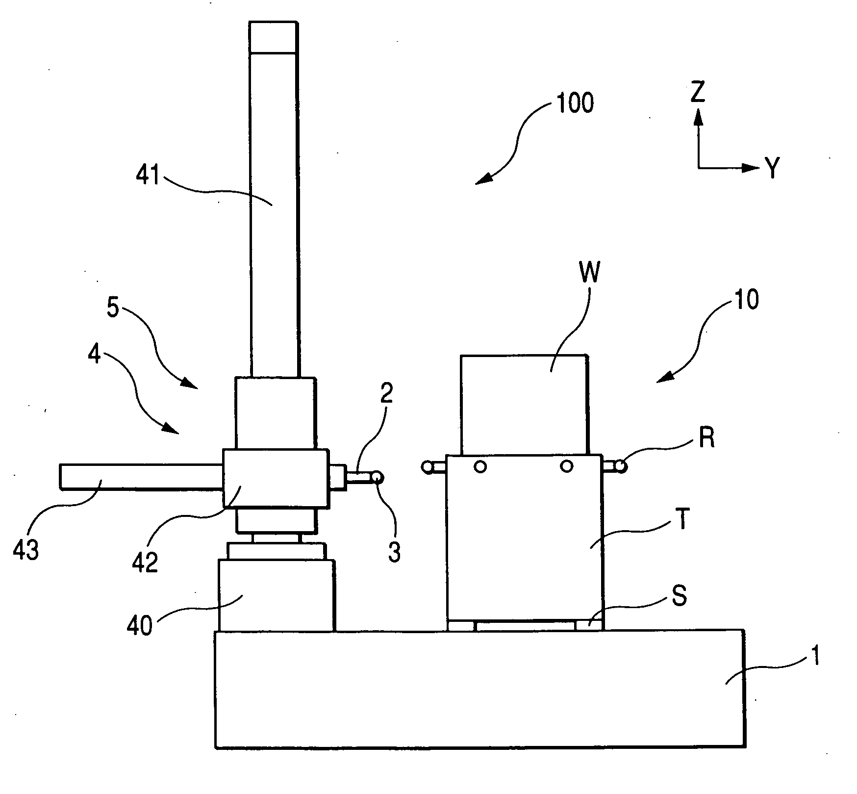
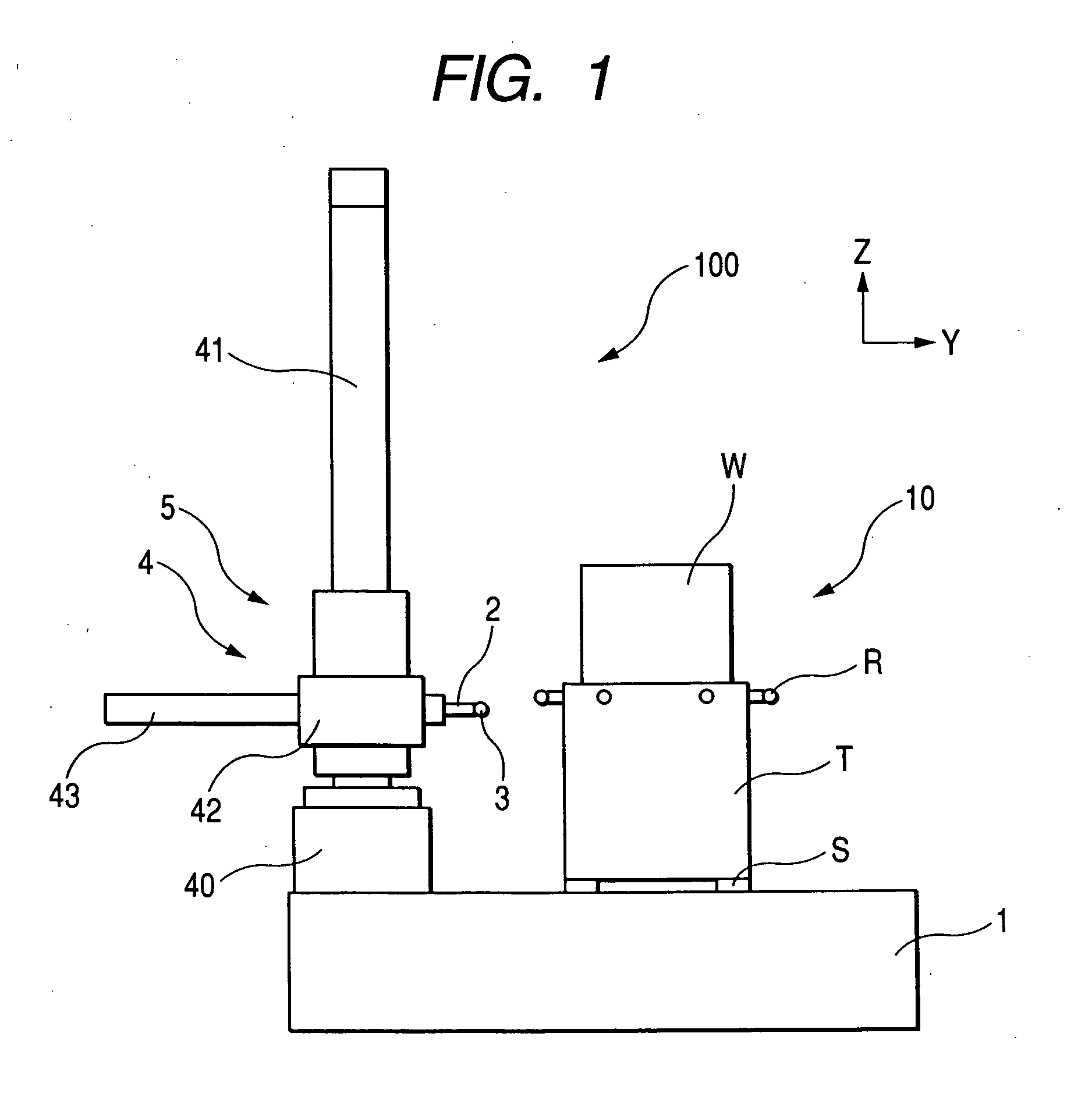
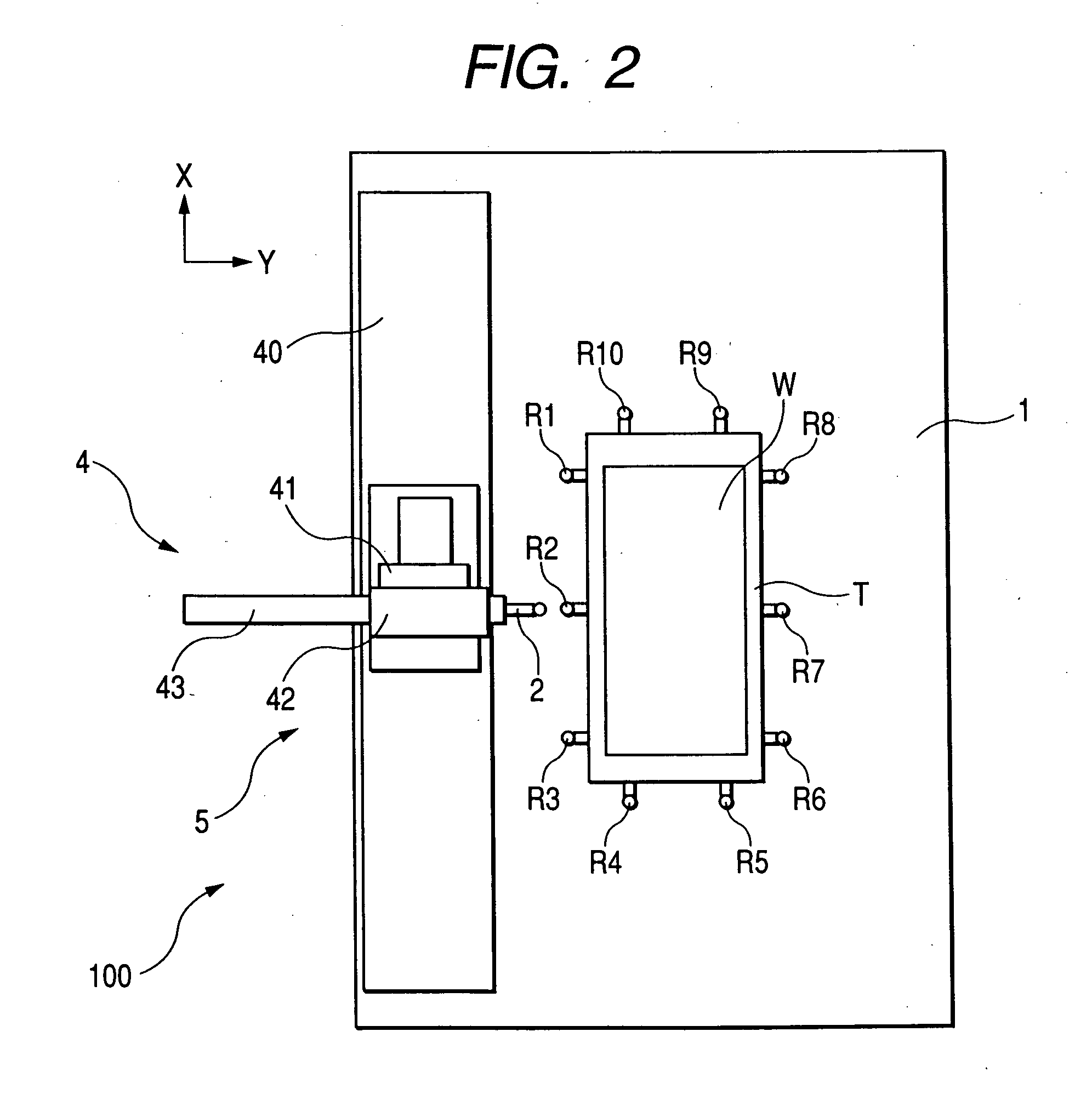
[0049]FIG. 1 is a side view of a surface texture measuring machine 100 in which a mount table 10 according to a first exemplary, non-limiting embodiment of the present invention is mounted on a base 1 as a surface plate. FIG. 2 is a plan view thereof.
[0050] An upper surface of a table main body T of the mount table 10 serves as a workpiece mount surface and a workpiece W is mounted thereon. On the upper parts of the side surfaces of the table main body T, a plurality of artifacts R are disposed at prescribed intervals on the periphery of the mount table T so that supports Rt having reference balls Rs at their ends protrude sideward (rightward and leftward of a sheet surface and vertical directions of the sheet surface in FIG. 1) (see FIG. 3). The relative positional relation of the central positions of the plurality of the reference balls Rs is previously precisely measured.
[0051] On the lower surface of the table main body T, air bearings as support units S are disposed at four c...
second embodiment
[0081] Now, by referring to FIG. 9, a surface texture measuring machine according to a second exemplary, non-limiting embodiment of the present invention will be described.
[0082] In the mount table 10 shown in the first exemplary, non-limiting embodiment, on the upper parts of the side surfaces of the table main body T, a plurality of artifacts R are disposed at prescribed intervals on the periphery of the mount table T so that supports Rt having reference balls Rs at their ends protrude sideward (rightward and leftward of a sheet surface and vertical directions of the sheet surface shown in FIG. 1). However, in the second exemplary, non-limiting embodiment, artifacts include reference plates Rp shown in FIG. 9 in place of the reference balls Rs and the supports Rt.
[0083] Since other points are the same as those of the first exemplary, non-limiting embodiment, an explanation thereof is omitted.
[0084] The reference plate Rp has a form of a rectangular parallelepiped finished to be...
third embodiment
[0093] Now, a surface texture measuring machine according to a third exemplary, non-limiting embodiment will be described by referring to FIG. 11.
[0094] The mount table 10 shown in the first exemplary, non-limiting embodiment only has the mount surface on which the workpiece W is mounted on its upper part. However, in the third exemplary, non-limiting embodiment, a mount table 30 has a sucking unit for sucking a workpiece W on the mount surface of the mount table 30.
[0095] Other points are the same as those of the first exemplary, non-limiting embodiment, an explanation thereof is omitted.
[0096]FIG. 11 shows a section of the mount table 30. A sucking unit C is provided on the upper part of a table main body T of the mount table 30.
[0097]FIG. 12 shows a section of the sucking unit C. The sucking unit C has a substantially rectangular form in its horizontal section. In an outer tube C0, a suction pad C1, a gap part C2 and a piping connecting part C3 are incorporated. The piping co...
PUM
 Abstract
Description
Claims
Application Information