Laryngoscope

a technology of laryngoscope and ophthalmology, which is applied in the field of laryngoscope, can solve the problems of insufficient alignment of analogous types of couplings, inability to quickly change spatulas, and inability to fold up, etc., and achieves the effect of precise alignment of the handle and simple design measures

Inactive Publication Date: 2005-03-17
ELAN SCHALTELEMENTE
View PDF18 Cites 33 Cited by
  • Summary
  • Abstract
  • Description
  • Claims
  • Application Information

AI Technical Summary

Benefits of technology

[0007] The present invention is based on the object of designing a laryngoscope of the above kind in such a way that it ensures that the spatula and handle are aligned in relation to each other so precisely that image distortions are excluded, yet at the same time offer the possibility of detaching the tongue and handle from each other. Additionally, through simple design measures, the spatula shall be able to pivot on the handle without causing uncontrolled detaching. The precise alignment between handle and spatula can be implemented with simple measures, wherein it shall be possible to swivel and fix the spatula and handle with one hand.

Problems solved by technology

In practice it has been shown that the analogous types of coupling are not sufficient to adequately align the image conductor precisely with the video input opening existing in the handle in order to avoid image distortions and / or exclude that the picture drifts.
With bayonet and screw couplings a quick change of spatulas is not feasible.
A folded-up position, snug against the handle, for transport purposes is also not possible.

Method used


Image

  • Laryngoscope
  • Laryngoscope
  • Laryngoscope

Examples


Embodiment Construction

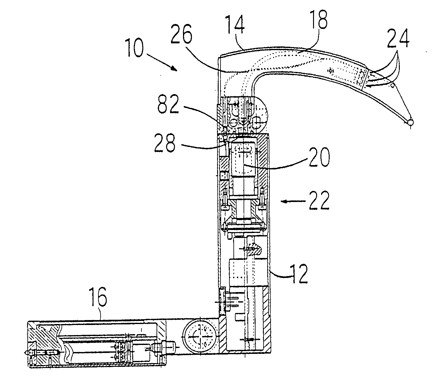
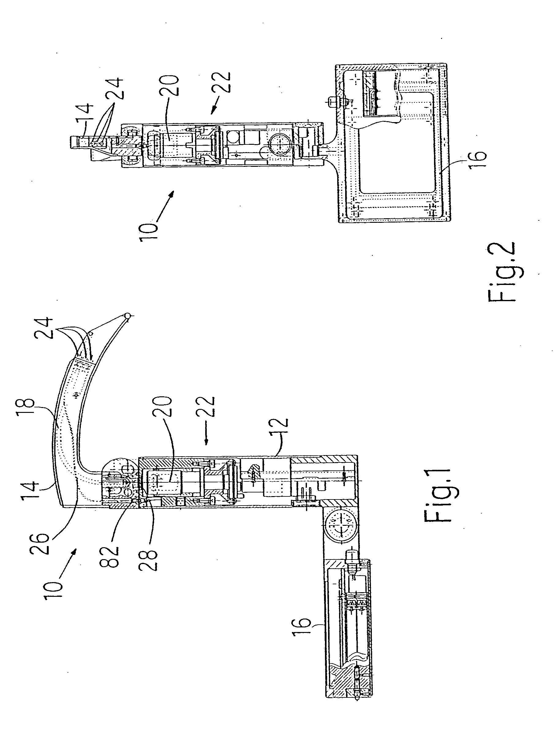
[0023] In FIGS. 1 and 2 the sectional views of a laryngoscope 10 are illustrated, which insofar represents a classic design that the laryngoscope 10 consists of a handle 12 and a spatula 14 that is detachably connectable thereto. An LCD monitor 16 extends detachably from the proximal end of the handle 12, wherein said monitor according to the illustrations in FIGS. 1 and 2 can pivot.

[0024] Images can be depicted on the screen of the LCD monitor 16, which are transmittable to an image processing unit 22 via an image conductor 18 and an optical element 20. As a result, a pictures are taken of the throat cavity of a patient by using the laryngoscope 10. For this purpose, the image conductor ends in the area of the distal end of the spatula 14. In addition, a light source is provided in the distal area of the spatula 14, in the form of a light-emitting diode 24, which is supplied with the required voltage via a guide 26. The voltage source can be located inside the handle 12.

[0025] To...


PUM


Abstract

A laryngoscope including a handle and a spatula that is detachably connected thereto via a coupling. So that an image can be transmitted free of distortion over an image conductor from the spatula in the handle, spatula and handle are connected via first and second projections. The projections make it possible to twist the spatula in relation to the handle as well as snap-fit them to each other.

Description

BACKGROUND OF THE INVENTION [0001] The invention relates to a laryngoscope, comprising a handle and a spatula that is detachably connected thereto via a coupling, a light-emitting element arranged in the spatula an image conductor running through the spatula, which in the area of the coupling can be aligned with a video input opening arranged in the handle, which is assigned to a video recording device arranged in the handle, wherein the coupling has at least one mechanical centering element for precisely aligning the image conductor with the video input opening. [0002] An analogous laryngoscope can be found in DE 199 55 180 A1. In order to precisely align an image conductor extending from the spatula with a lens system arranged in the handle, the mechanical centering element has a cone as well as a corresponding countercone, of which one is arranged on the handle and the other on the spatula. These measures are intended to enable a rigid attachment of one to the other in a radial a...

Claims


Application Information

Patent Timeline
Patent Type & Authority Applications(United States)
IPC IPC(8): A61B1/267
CPCA61B1/267
Inventor ZILCH, PETER
Owner ELAN SCHALTELEMENTE
Why Eureka
Try Eureka