
Sensor device for measuring torque in steering systems

a technology of steering system and sensor device, which is applied in the direction of mechanical control device, controlling member, instruments, etc., can solve the problems of lower detection accuracy of magnetic field change detected by magnetic field sensor, and consequently less accurate signal supplied by sensor, etc., and achieves compact design and simple design measures.

Inactive Publication Date: 2011-10-20
ROBERT BOSCH AUTOMOTIVE STEERING
View PDF13 Cites 2 Cited by
  • Summary
  • Abstract
  • Description
  • Claims
  • Application Information

AI Technical Summary

Benefits of technology

It is an object of the invention to refine a sensor device for capturing torque in steering systems of vehicles, using simple design measures, so that the torque signal generated is as accurate as possible, with a compact design.
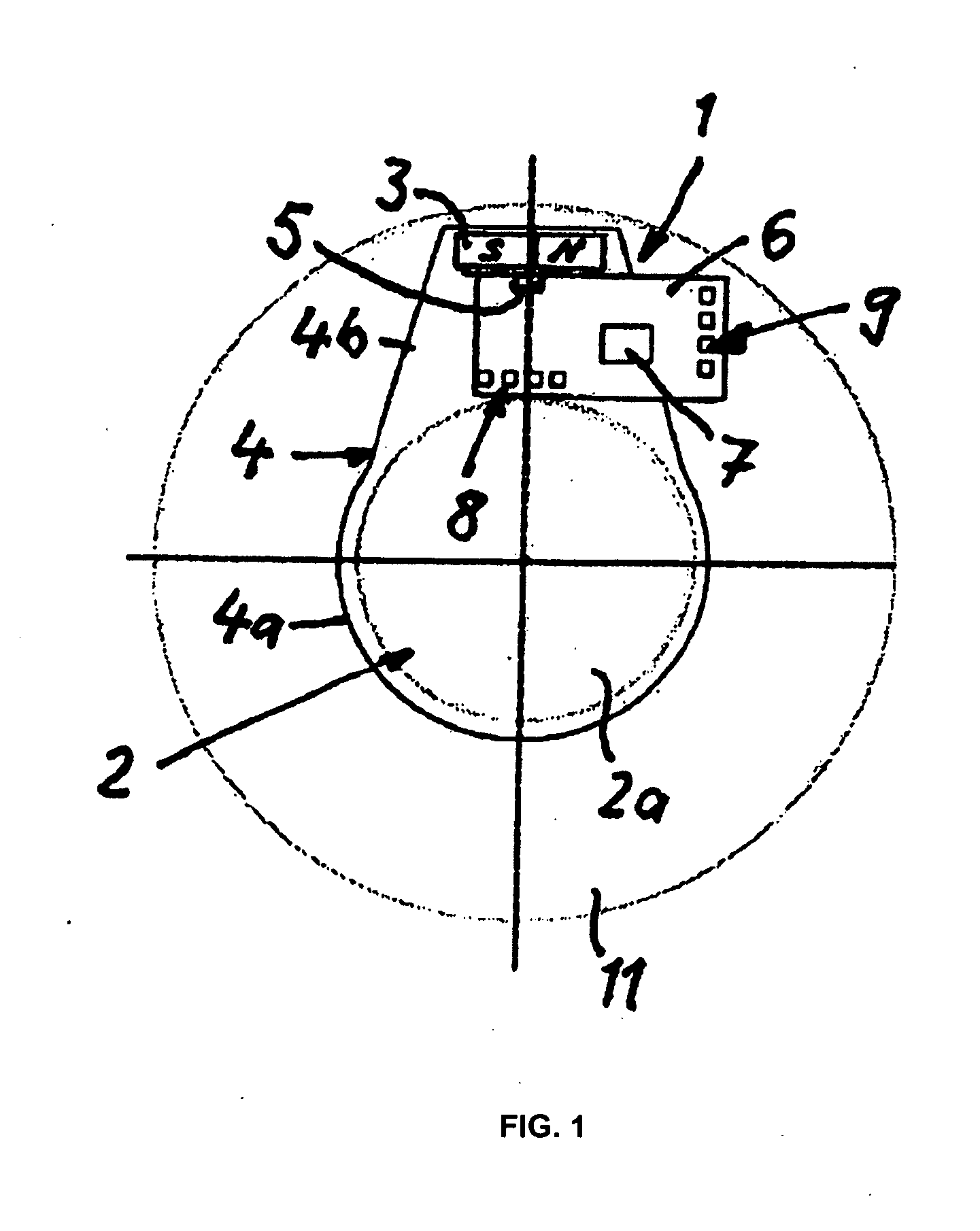
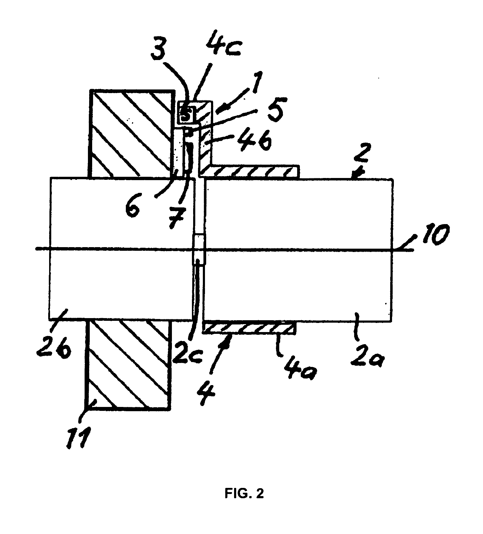
According to the invention, the magnet holder carrying the magnet comprises a receiving region disposed at a radial distance from the shaft, and the magnet is disposed on the inside of the receiving region facing the shaft. This constitutes a departure from prior art designs, in terms of the arrangement of the magnet in relation to the shaft or the magnet holder. With the design according to the invention, the magnet is located on the inside of the receiving region in the magnet holder and faces the shaft, while in designs according to the prior art the magnet is disposed at the exterior of the magnet holder and is directed radially outward. Compared to the prior art, the novel arrangement according to the invention has the advantage that the magnet is at a relatively large radial distance from the shaft, despite the compactness overall design, so that angular changes of the shaft result in a relatively large travel of the magnet, and thus a significant change in the magnetic field can be detected, which positively affects the quality of the measurement signal.
According to a preferred embodiment, in addition, the magnetic field sensor is at a radial distance, with respect to the rotational axis of the shaft, that is no greater than that of the magnet, whereby a compact design can also be achieved in the radial direction. To this end, the magnetic field sensor is either seated radially in the interposed region between the exterior of the shaft and the magnet, so that the sensor is shielded to the radial exterior by the magnet, or the magnetic field sensor is located at an axial distance from the axial end face of the magnet. In both cases, the sensor is located within the radius that is determined by the exterior of the magnet. Disposing the sensor between the exterior of the shaft and the magnet is also advantageous in that a very compact design is further achieved in the axial direction, because it is generally unnecessary for the sensor to protrude axially beyond the magnet.
Because of the optimized arrangement, a signal improvement of roughly up to 50% is achieved with the same installation space size. Conversely, it is also possible to achieve a significant reduction in the installation space with the same signal quality.
According to an advantageous embodiment, the magnet has a segment-shaped configuration, notably in a rectangular shape or shaped as a circular segment, so that ring-shaped magnets are no longer required. Nonetheless, it may be advantageous to provide a ring-shaped magnet.
Notably in combination with a segment-shaped magnet, it is advantageous to design the receiving region of the magnet holder carrying the magnet in a trapezoidal shape, with the narrow side of the trapezoid being located on the radial exterior and the wide side being located adjacent to the shaft.

Problems solved by technology

There is a trend toward using increasingly rigid shafts in steering systems, but in terms of torque measurement this creates a problem in that the shaft produces lower torsion at a particular torque, and thus the change in the magnetic field detected by the magnetic field sensor is also lower.
The signal supplied by the sensor is accordingly less accurate.

Method used


Image

  • Sensor device for measuring torque in steering systems
  • Sensor device for measuring torque in steering systems
  • Sensor device for measuring torque in steering systems

Examples


Embodiment Construction

In the figures, identical components are denoted by the identical reference numerals.

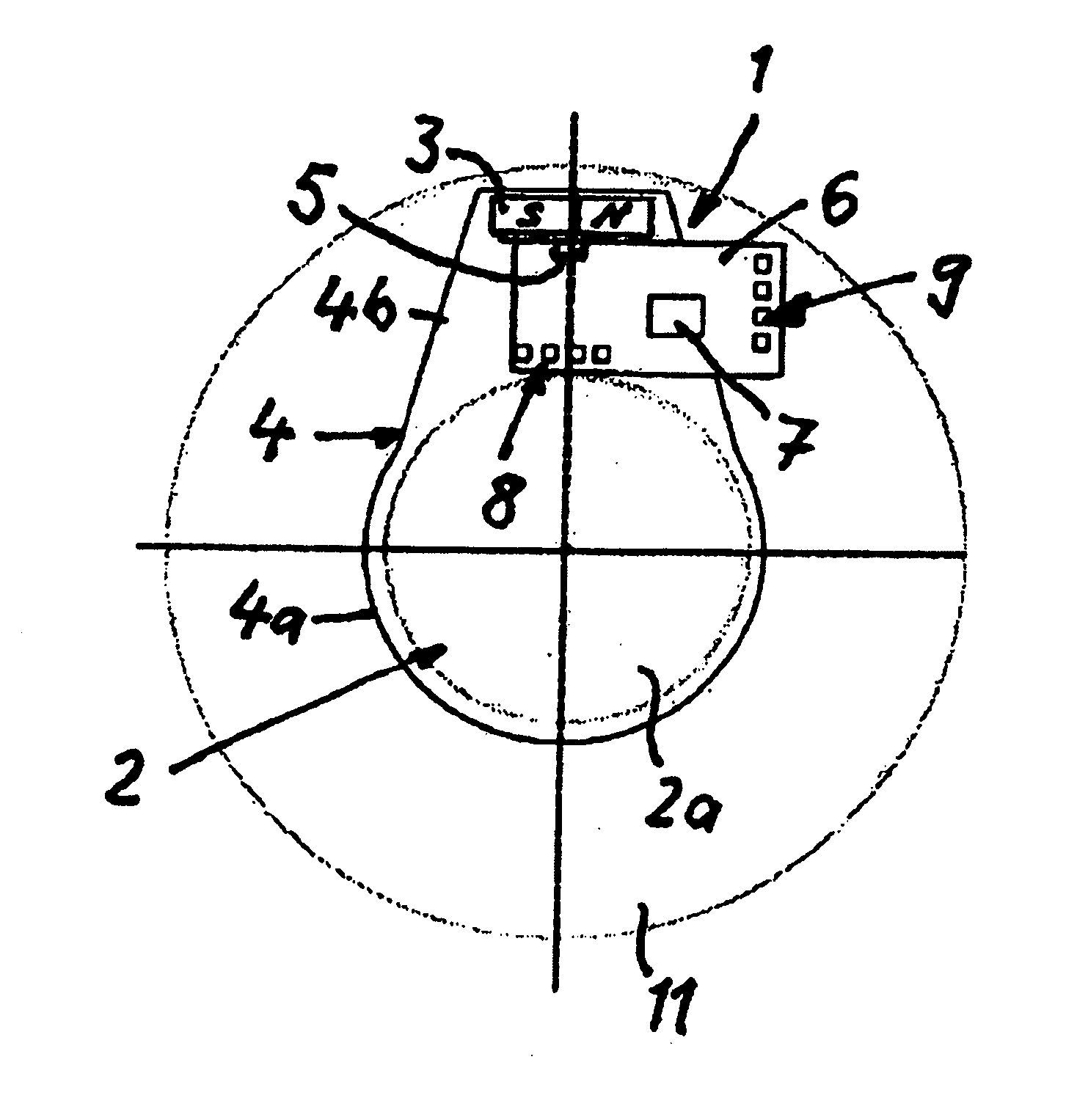
FIGS. 1 and 2 show a first embodiment. According to this embodiment, a sensor device 1 is provided for detecting the torque acting in a shaft 2, wherein the shaft 2 comprises an input shaft 2a, an output shaft 2b and a connecting torsion bar 2c. The torque to be measured acts between the input and output shafts 2a and 2b, which results in torsion in the torsion bar 2c. The torsion is determined by means of the torque sensor device 1 as a measure of the effective torque.

The sensor device 1 comprises a segment-shaped dipole magnet 3, which is rigidly connected to the input shaft 2 by way of a magnet holder 4. The N and S poles of the magnet 3 are located opposite of each other, radially or in the circumferential direction. In addition, the sensor device 1 comprises a magnetic field sensor 5, which is able to detect changes in the magnetic field originating from the magnet 3, which result from relative...


PUM

PropertyMeasurementUnit
magnetic fieldaaaaaaaaaa
magneticaaaaaaaaaa
torqueaaaaaaaaaa

Abstract

A sensor device for measuring torque in steering systems of vehicles comprises a magnet that is disposed on a shaft in a rotationally fixed manner, and a magnetic field sensor. The magnet is held by a magnet holder, which is to be connected to the shaft, wherein the magnet holder comprises a receiving region disposed at a radial distance from the shaft and the magnet is disposed on the inside of the receiving region facing the shaft.

Description

BACKGROUND OF THE INVENTIONThe invention relates to a sensor device for measuring torque in steering systems of vehicles.DE 101 27 169 B4 describes a steering system for a motor vehicle, which is equipped with an electric servomotor for steering assistance. Establishing the amount of the assistance torque requires knowledge of the torque presently acting on the steering shaft, which is determined by means of a sensor device.Sensor devices for measuring torque used in steering systems are typically magnet-based systems, which comprise a magnet that is disposed on the shaft in a rotationally fixed manner and a magnetic field sensor that is fixed to the housing or connected to a second part of the shaft in a rotationally fixed manner and is able to detect a change in the magnetic field during relative rotation. For example, Hall sensors or MR sensors are sensors that are used. On the shaft side, magnetic rings having a plurality of poles are used, which are seated on the shaft either d...

Claims


Application Information

Patent Timeline
Patent Type & Authority Applications(United States)
IPC IPC(8): B62D1/02G01L3/10
CPCY10T74/20396G01L3/104
Inventor ABELE, WOLFGANG
Owner ROBERT BOSCH AUTOMOTIVE STEERING
Learn More