Endoscopic device

a technology of endoscopic devices and connectors, applied in the field of endoscopic devices, can solve problems such as connector connection errors, and achieve the effect of eliminating connection errors and facilitating connection to the balloon control devi

Active Publication Date: 2010-03-16
SRJ +1
View PDF11 Cites 32 Cited by
  • Summary
  • Abstract
  • Description
  • Claims
  • Application Information

AI Technical Summary

Benefits of technology

[0009]According to the first aspect of the invention, the three ducts are connected to the balloon control device via one connector, thereby reducing the number of connectors as compared with the case where a connector is provided for each duct. This facilitates connection of the connector, and eliminates connection errors of the connector.
[0011]According to the second aspect of the invention, the connector portion of the endoscope is connected to the external device to simultaneously connect the three ducts to the balloon control device. This further facilitates connection of the connector. The external device is a light source device or a processor for the endoscope, and the connector portion of the endoscope is a so-called light guide connector or an electric connector.
[0013]According to the third aspect of the invention, the three ducts are connected to the connector portion of the endoscope, and thus the connector portion and the balloon control device are simply connected by the tube to allow the three ducts to be connected to the balloon control device. This facilitates connection of the connector, and eliminates connection errors of the connector.
[0015]In the endoscopic device according to the invention, the first duct that communicates with the first balloon, the second duct that communicates with the second balloon, and the third duct through which the lubricant is supplied are connected to the balloon control device via one connecter, or the three ducts are connected to the connector portion of the endoscope connected to the external device and then connected to the balloon control device. This facilitates connection to the balloon control device, and eliminates connection errors.

Problems solved by technology

Thus, the conventional endoscopic device includes many connectors and takes trouble in connecting the connectors, and may cause connection errors of the connectors.

Method used


Image

  • Endoscopic device
  • Endoscopic device
  • Endoscopic device

Examples


first embodiment

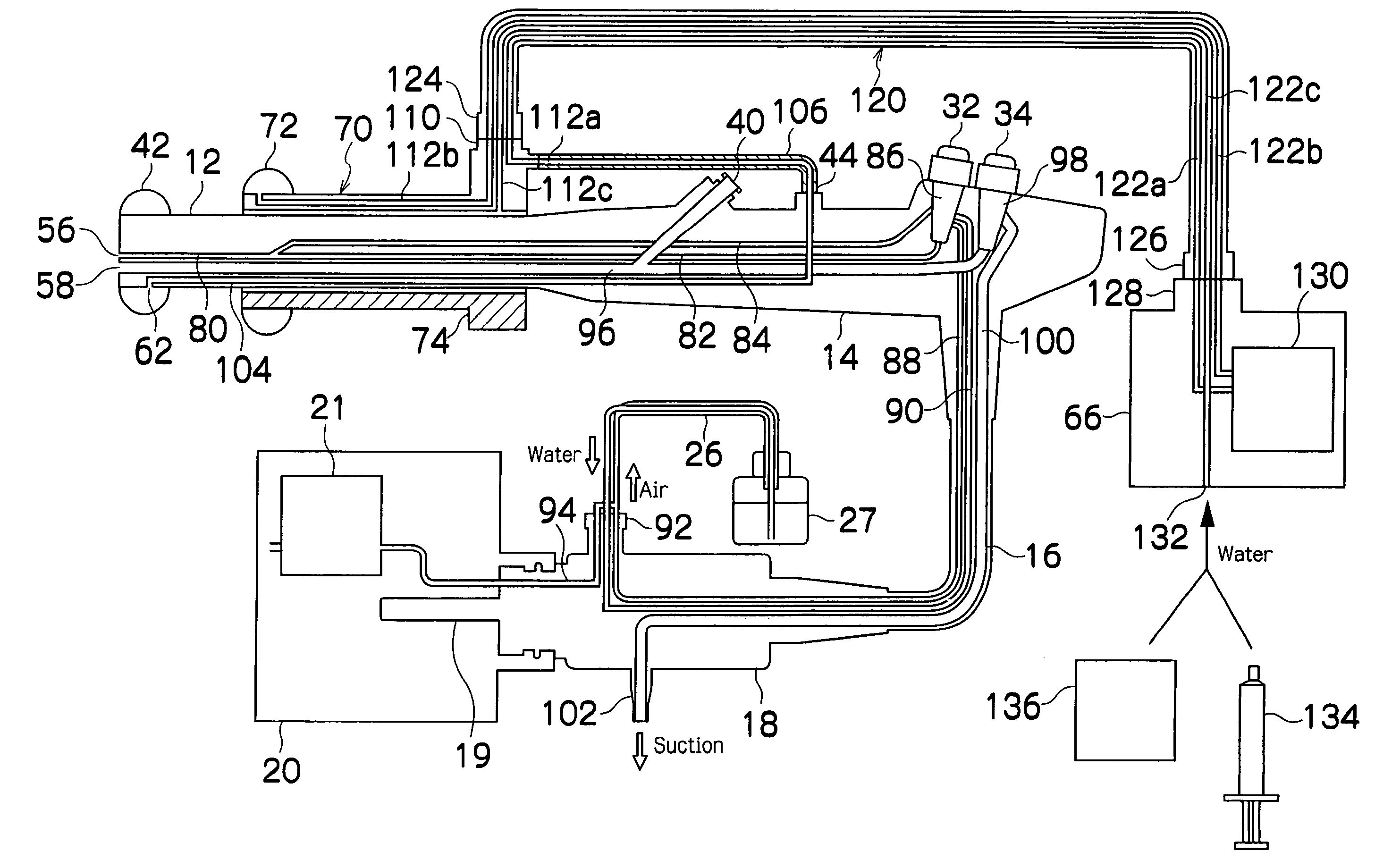
[0045]The invention is not limited to the configuration of the first embodiment, but may have a configuration in which a first duct that communicates with a first balloon 42, a second duct that communicates with a second balloon 72, and a third duct through which a lubricant is supplied are correctively connected to one connector. For example, as shown in FIG. 4, a duct 122a only may be branched in the middle of a tube 120, and the branched portion is directly connected to a supply / suction port 44 of an endoscope 10.

second embodiment

[0046]FIG. 5 is a schematic configuration diagram of ducts for a fluid in an endoscopic device according to a

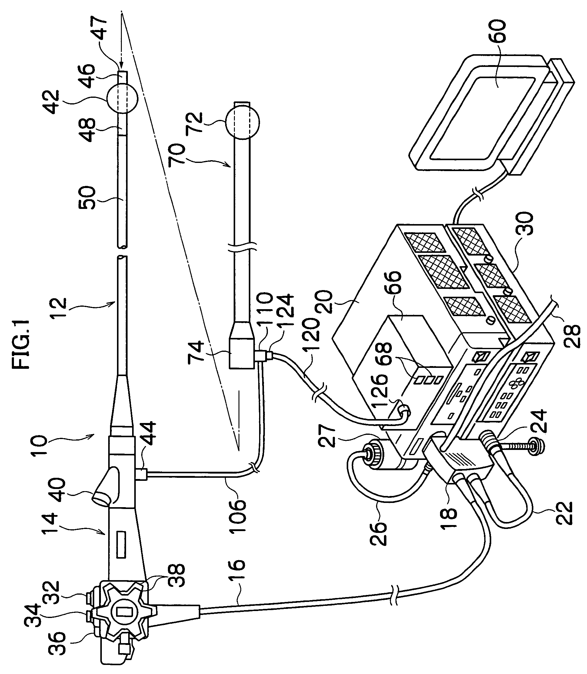
[0047]As shown in FIG. 5, ducts 112b and 112c are connected to a connector 110 of an insertion aid member 70. An end connector 144 of a tube 140 is connected to the connector 110. Two ducts 142b and 142c are formed in the tube 140, and the ducts 142b and 142c communicate with the ducts 112b and 112c, respectively. The other end connector 146 of the tube 140 is connected to a connector 148 of a hand operation portion 14. Tubes 150b and 150c are connected to the connector 148, and the tubes 150b and 150c communicate with the ducts 112b and 112c, respectively. The tubes 150b and 150c each are inserted through a universal cable 16, and extended to a connection surface 17 of an LG connector 18. A tube 104 that communicates with a first balloon 42 is extended to and placed in the connection surface 17.

[0048]A light source device 20 has a function of the balloon control device 66 in...

third embodiment

[0055] configured as described above, the tube 170 is simply connected to the LG connector 18 and the balloon control device 66 to allow the three ducts to be simultaneously connected, thereby facilitating connection of the connector and eliminating connection errors.

[0056]In the third embodiment, like the second embodiment, the three ducts are inserted through the universal cable 16, and a small number of cords are drawn out of a hand operation portion 14, thereby improving operability of the hand operation portion 14.

[0057]In the third embodiment, the three ducts are extended to the LG connector 18, but the present invention is not limited to this. That is, the ducts may be extended to a connector portion of an endoscope 10 connected to an external device. For example, the three ducts may be extended to the electric connector 24 in FIG. 1.


PUM


Abstract

A first balloon is fitted to an insertion portion of an endoscope and a second balloon is fitted to an insertion aid member. An end connector of a tube is connected to a balloon control device that supplies and sucks air into and from the first balloon and the second balloon. A duct that communicates with the first balloon, a duct that communicates with the second balloon, and a duct that communicates with a clearance between the insertion portion and the insertion aid member are formed in the end connector.

Description

BACKGROUND OF THE INVENTION[0001]1. Field of the Invention[0002]The present invention relates to an endoscopic device, and more particularly to an endoscopic device that alternately inserts an insertion portion of an endoscope and an insertion aid member to insert the insertion portion into an alimentary canal in a deep part such as small intestine or large intestine for observation.[0003]2. Related Art[0004]When an insertion portion of an endoscope is inserted into an alimentary canal in a deep part such as small intestine, complex bending of intestine prevents a force from being transmitted to a tip of the insertion portion in simple insertion of the insertion portion, and insertion into a deep part is difficult. For example, surplus bending or flection in the insertion portion prevents the insertion portion from being further inserted into the deep part. Thus, a method is proposed for inserting an insertion portion of an endoscope covered with an insertion aid member into a body ...

Claims


Application Information

Patent Timeline
Patent Type & Authority Patents(United States)
IPC IPC(8): A61B1/00A61B1/06A61F2/958
CPCA61B1/00082A61B1/00119A61B1/00156A61B1/00154A61B1/00128
Inventor FUJIKURA, TETSUYA
Owner SRJ
Why Eureka
Try Eureka