Multiple receiver aggregation

a technology of multiple receivers and aggregation, applied in the field of wireless communication, can solve the problems of affecting the reliability and feasibility of multiple receivers, affecting the distribution and affecting the reliability of multiple acks or bas after the sifs,

a technology of multiple receivers and aggregation, applied in the field of wireless communication, can solve the problems of affecting the reliability and feasibility of multiple receivers, affecting the distribution and affecting the reliability of multiple acks or bas after the sifs,

US20050226273A1Active Publication Date: 2005-10-13CISCO SYSTEMS INC

Image

  • Multiple receiver aggregation
  • Multiple receiver aggregation
  • Multiple receiver aggregation

Examples


Embodiment Construction

[0022] Throughout this description, the preferred embodiment and examples shown should be considered as exemplars, rather than limitations, of the present invention.

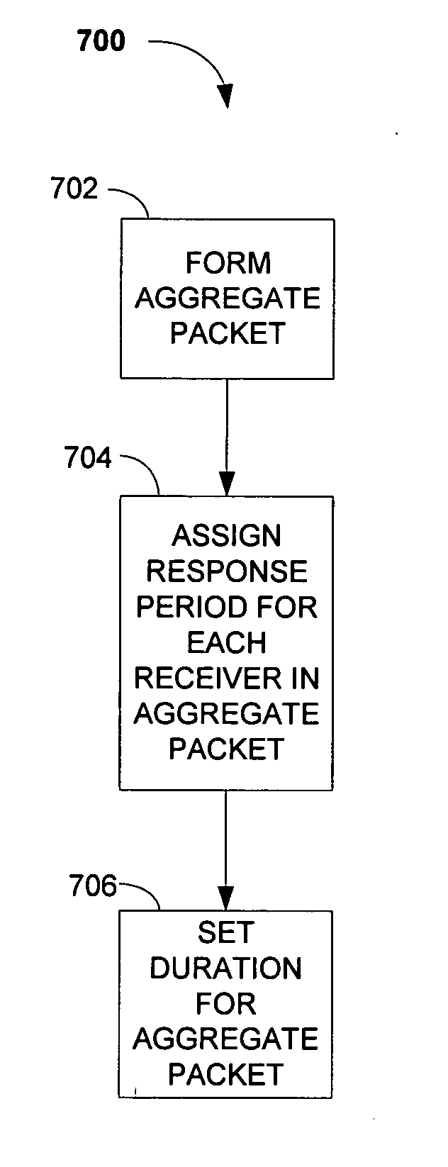
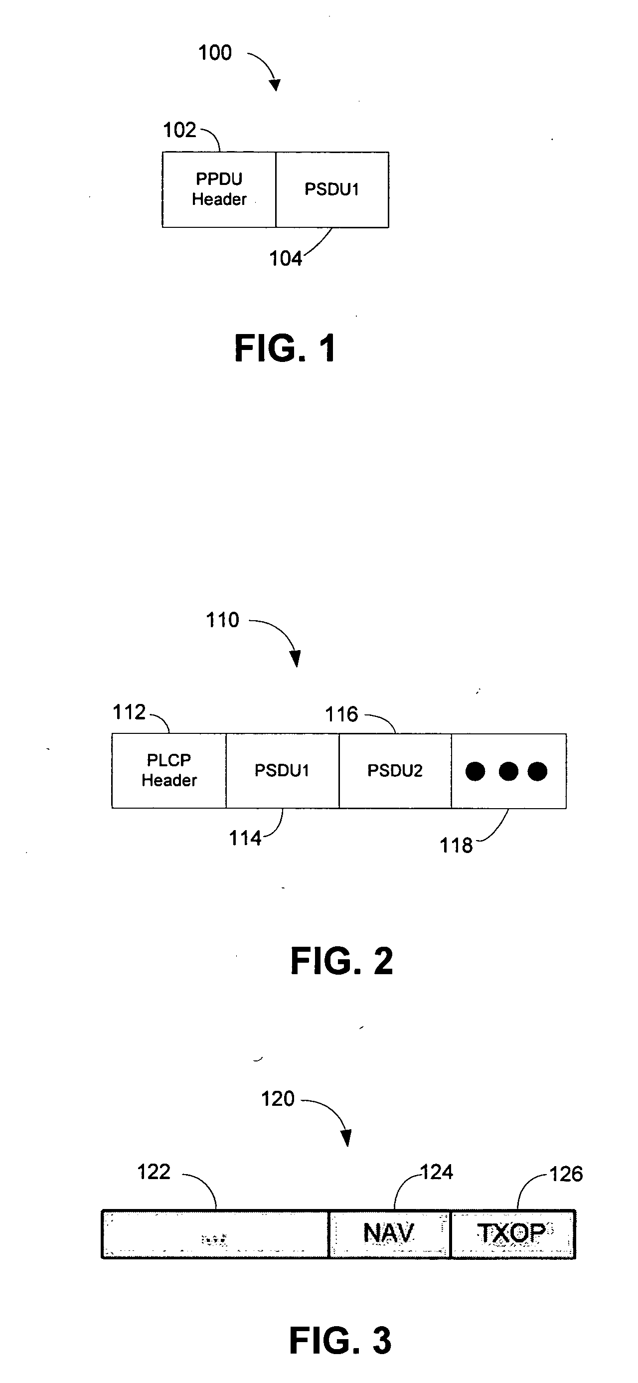
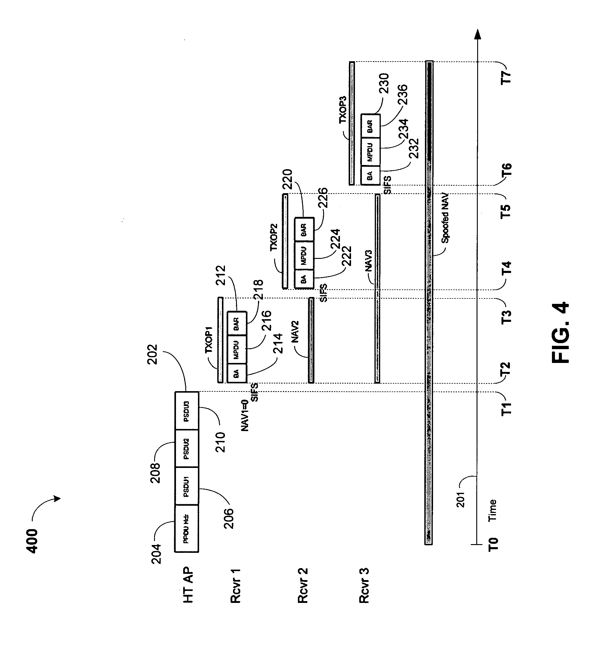
[0023] The present invention is a multiple receiver aggregation (MRA) technique that allows for multiple immediate responses of acknowledgements (ACKs) or block acknowledgements (BAs). The present invention uses a spoofed NAV implemented within the aggregate's PLCP header to protect the aggregate and all of the immediate responses from the multiple receivers. The immediate responses from the multiple receivers are scheduled. The scheduling information is included in the PSDU headers contained within the aggregate.

[0024] By using various aspects of the present invention, a transmitter (e.g., high throughput “HT” transmitter) can send aggregates to multiple receivers (e.g., HT receivers) and request immediate ACKs / BAs from all or some of the addressed receivers. The receiver can attach an aggregate MPDU to the transmitte...


PUM


Abstract

A technique for multiple receiver aggregation that allows for multiple immediate responses of acknowledgements or block acknowledgements. The technique uses a spoofed network allocation vector (NAV) implemented within an aggregate's PLCP header to protect the aggregate and all of the immediate responses from multiple receivers. The immediate responses are scheduled, the information indicating the scheduled offset time and granted transmission duration for response of each receiver being included in the physical sublayer data unit (PSDU) headers within the aggregate.

Description

CROSS-REFERENCE TO RELATED APPLICATION [0001] This application claims the benefit of priority of U.S. Provisional Application No. 60 / 560,303 filed Apr. 7, 2004.BACKGROUND OF THE INVENTION [0002] The present invention relates generally to wireless communications and more specifically to techniques for multiple receiver aggregation with multiple responses. [0003] Multiple receiver aggregation (MRA) is useful in the Media Access (MAC) Layer to achieve high throughput (HT) for next generation 802.11 wireless networks. For example, an 802.11n MRA aggregate sends one large frame, a Physical Layer Protocol data unit (PPDU), containing multiple Physical Layer Service Data Units (PSDUs) to one or more receivers. Each receiver responds with an acknowledgement (ACK) or block ACK (BA) indicating the PSDUs were received. However, there are many challenges though in obtaining a reliable and feasible form of MRA. Hidden nodes, for example, can make it almost impossible for multiple receivers to re...

Claims


Application Information

Patent Timeline
13 Oct 2005
Publication
US20050226273A1
IPC
H04L12/28
CPC
H04L1/1628; H04W74/04; H04W28/06
Inventors
QIAN, LU