Apparatus and method for transmission and recovery modes for an rts/cts system that utilizes multichannels

a multi-channel, transmission mode technology, applied in the field of apparatus and methods for wireless systems, can solve the problem of resetting the duration of the nav

Active Publication Date: 2013-03-21
QUALCOMM INC
View PDF9 Cites 21 Cited by
  • Summary
  • Abstract
  • Description
  • Claims
  • Application Information

AI Technical Summary

Problems solved by technology

A problem exists in the RTS/CTS protocol for multichannel wireless systems, in which the CTS ban

Method used


Image

  • Apparatus and method for transmission and recovery modes for an rts/cts system that utilizes multichannels
  • Apparatus and method for transmission and recovery modes for an rts/cts system that utilizes multichannels
  • Apparatus and method for transmission and recovery modes for an rts/cts system that utilizes multichannels

Examples


first embodiment

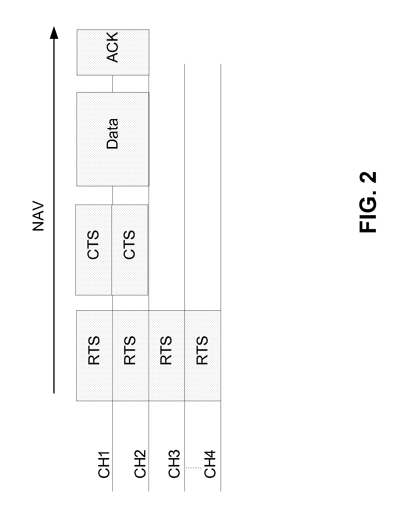
[0026]In an example that uses the first embodiment, as shown in FIG. 2, since the CTS frame is sent only on channels CH1 and CH2, which is a smaller bandwidth (e.g., 40 MHz) than the RTS bandwidth (e.g., 80 MHz), data is sent by the source node on the smaller bandwidth indicated by the CTS frame, and the amount of data that can be sent from the source node 100 to the destination node 110 is recomputed by each node receiving the RTS frame and CTS frame based on the NAV originally set by the RTS frame and the new, smaller bandwidth as provided in the CTS frame. That is, in the example shown in FIG. 2, because the NAV duration is set based on the RTS frame, the amount of data that can be sent is halved (e.g., from 1 GHz to 500 MHz), since the NAV duration remains the same. Once the NAV duration is finished, the RTS / CTS protocol allows for any node on the network to request to transmit over one or more channels to a destination node on the network, in a manner known to those of ordinary...

second embodiment

[0029]In a second implementation consistent with the second embodiment, the NAV duration is computed based on a minimum bandwidth and the amount of data to be sent from the source node 100 to the destination node 110, in which the minimum bandwidth may correspond to the bandwidth of only one channel in a multi-channel wireless environment. By way of example, this minimum bandwidth is 20 MHz, which the bandwidth of one channel. Other minimum bandwidth values may be utilized based on the channel requirements of a particular network, such as a minimum channel value of 1 MHz or 500 MHz, for example. In other implementations, the minimum bandwidth may correspond to a portion of a single channel, such as 5 MHz (¼ of a channel) in the example described herein.

[0030]In the second implementation consistent with the second embodiment, the NAV duration is set to a value based on the following equation:

NAV duration=Data Tx frame(s) time+CTS frame time+Ack frame time+3*SIFS,

[0031]in which the C...

third embodiment

[0036]In the third embodiment, the NAV duration is computed based on the bandwidth used by the RTS frame (e.g., the bandwidth of CH1, CH2, CH3 and CH4 combined) and the amount of data to be sent, subject to a maximum timeout limit (TXOP). In more detail, the NAV duration is set to a value equal to:

NAV duration=RTS1 frame time+Data Tx frame(s) time+CTS1 frame time+Ack frame time+3 SIFS.

[0037]In the third embodiment, the CTS1 frame is sent back from the destination node 110 to the source node 100 on the free channels with bandwidth information included. The CTS1 frame is preferably sent in duplicate mode with 11a preamble.

[0038]If the CTS1 frame is sent on a bandwidth smaller than the one included in the RTS1 frame, a second RTS2 / CTS2 exchange is performed between the source node 100 and the destination node 110, in which a new NAV duration is set to a value based on the bandwidth used by the RTS2 frame and the amount of data to be sent, subject to a maximum timeout duration (TXOP).

[...


PUM


Abstract

A method, apparatus and computer readable medium for an RTS/CTS system that utilizes a plurality of channels for data transfer, includes sending, by a first device, an RTS frame over the plurality of channels; receiving, by a second device, the RTS frame and outputting a CTS frame to the first device based on receipt of the RTS frame, the CTS frame being output over at least one of the plurality of channels; setting, by each device within a network that receives the RTS frame, a network allocation vector (NAV) to a time duration that is based in part on information included in the RTS frame; and transmitting, by the first device, data to the second device within the time duration set by the NAV using the at least one of the plurality of channels.

Description

BACKGROUND[0001]1. Field of the Disclosure[0002]This disclosure relates generally to apparatus and methods for a wireless system that utilizes the RTS / CTS protocol. More particularly, the disclosure relates to an apparatus and method for transmission and recovery modes for an RTS / CTS system that utilizes multiple channels.[0003]2. Related Art[0004]One type of wireless system is an RTS / CTS protocol system. In this system, a source node that desires to send data to a destination node over a communications channel sends a Request to Send frame (RTS) to the destination node over the communications channel. The RTS frame is also received by other nodes in the system that are in the vicinity of the sending node, and those other nodes should refrain from sending data for a given time, which is called a Network Access Vector (NAV) duration. The destination node sends back a Clear to Send frame (CTS) to the sending node, if it is available to receive data. The amount of time that a node shou...

Claims


Application Information

Patent Timeline
IPC IPC(8): H04W4/00
CPCH04W74/0816H04L12/413H04W84/12H04W74/08
Inventor MERLIN, SIMONEFREDERIKS, GUIDO ROBERTKANDALA, SRINIVASJONES, IV, VINCENT KNOWLES
Owner QUALCOMM INC
Why Eureka
Try Eureka