Level with cylindrical handle

Inactive Publication Date: 2005-10-20
KIM CHARLES D
View PDF13 Cites 17 Cited by
  • Summary
  • Abstract
  • Description
  • Claims
  • Application Information

AI Technical Summary

Benefits of technology

[0023] The cylindrical portion preferably defines a curvilinear surface and the hand-grip aperture is preferably defined by an aperture surface extending from the front surface portion to the rear surface por

Problems solved by technology

A problem with such apertures is that they require the user to grip a planar surface and, thus, the edges of the planar surface when carrying or holding the level by gripping the aperture.
While such a requirement may not seem too burdensome, the user may also be carrying other items in his hand and may be required to squeeze tightly to hold such items, causing the edges of the level t

Method used


Image

  • Level with cylindrical handle
  • Level with cylindrical handle
  • Level with cylindrical handle

Examples


Embodiment Construction

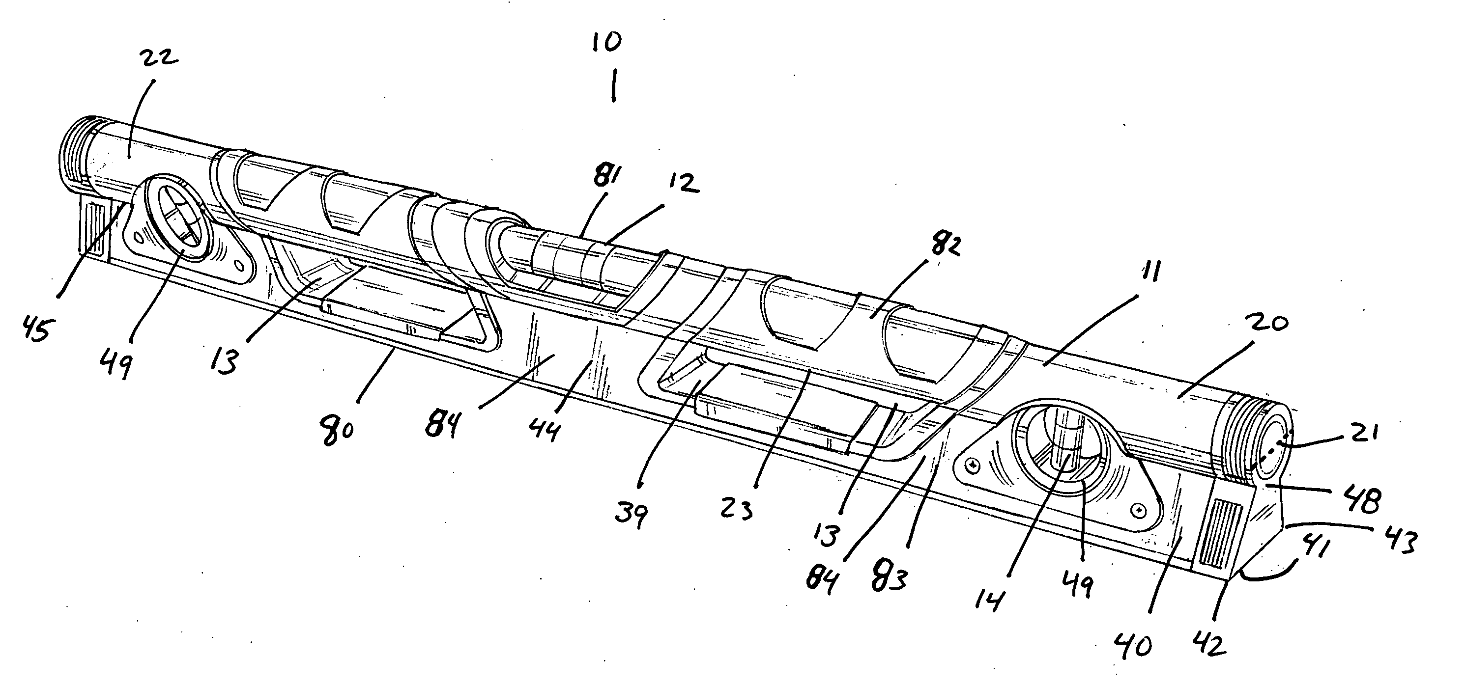
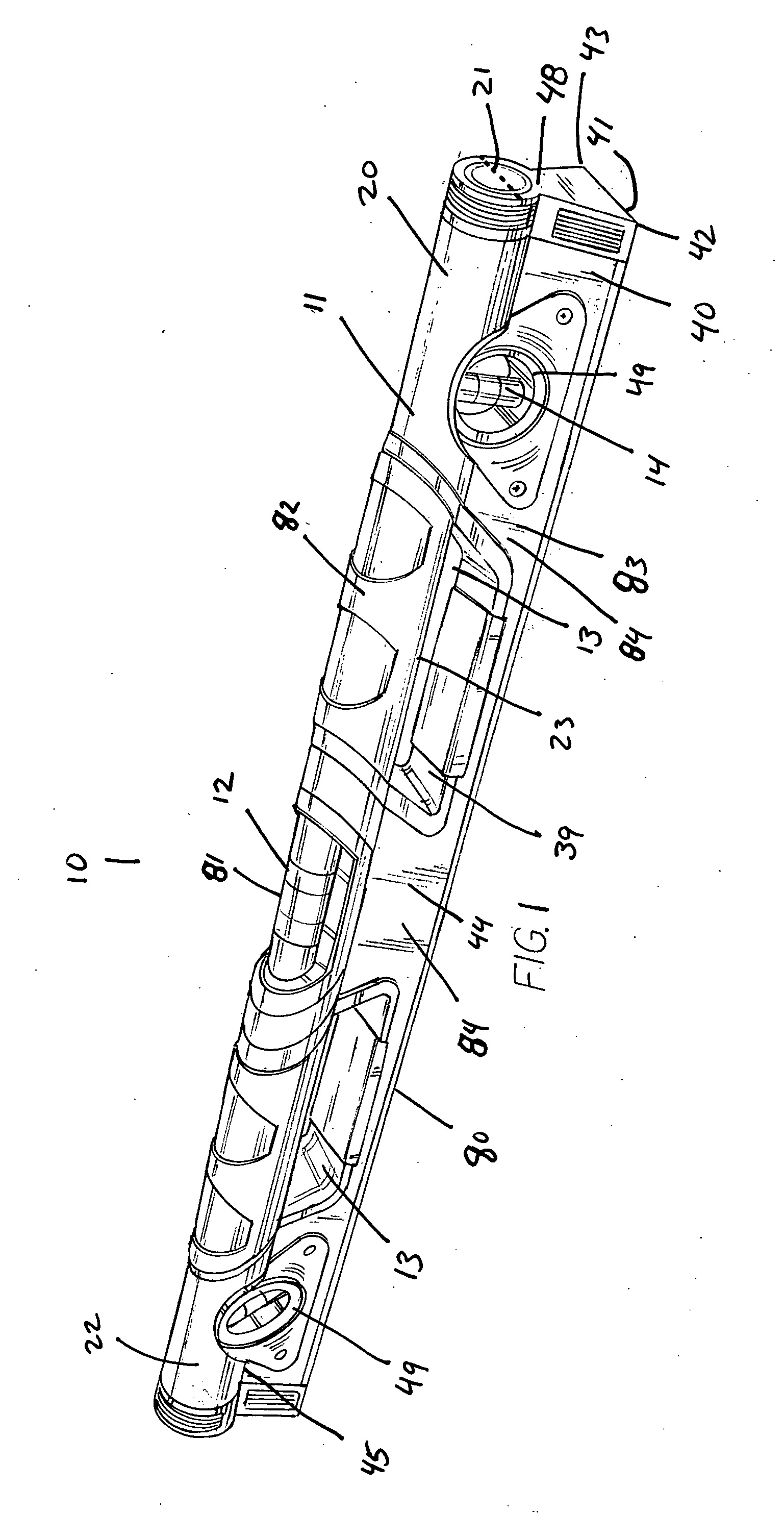
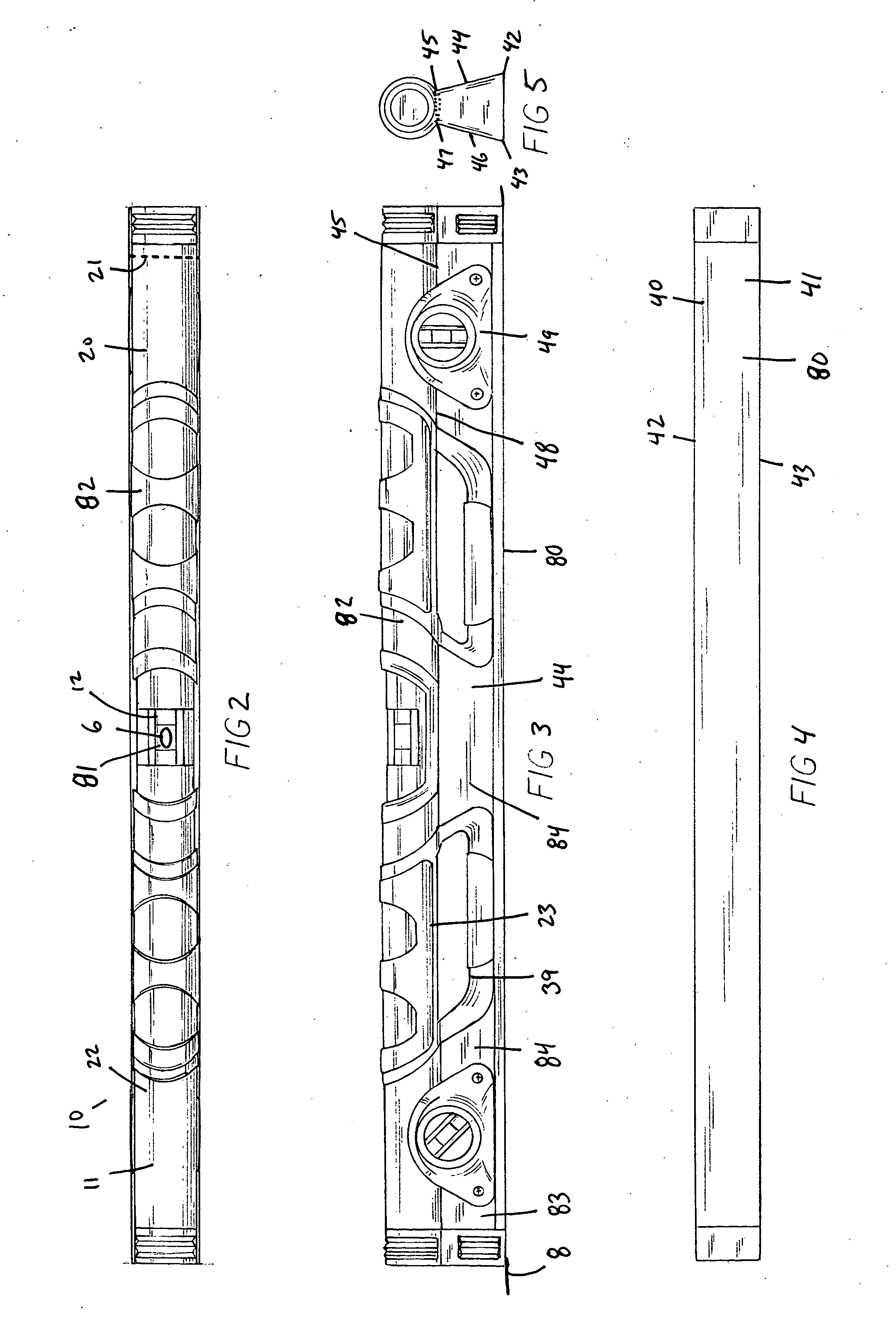
[0031]FIG. 1 is a perspective view of level 10. Level 10 includes a body 11 including a cylindrical portion 20 and a trapezoidal portion 40 which meet at interface 48. Cylindrical portion 20 has a circular cross section and a diameter 21 defining the width of cylindrical portion 20. Diameter 21 is parallel to level face 41 and may have a width greater than, equal to, or less than level face 41. Curvilinear surface 22 bounds cylindrical portion 20. First vial 12 is positioned within cylindrical portion 20.

[0032] Trapezoidal portion 40 includes a level face or face surface 41 which is used to contact an element, such as surface 8 (see FIG. 3), to determine its levelness. Face 41 extends from a first edge 42 to a second edge 43. A planar front surface portion 44 extends upward from first edge 42 at an acute angle to face 41 and terminates at front upper edge 45. A planar rear surface portion 46 (see FIG. 5) extends upward from second edge 43 at an acute angle to face 41 and terminates...


PUM


Abstract

A level for facilitating handling during use is disclosed. The level includes element-contacting means, level-indicating means mounted with respect to the element-contacting means; and a cylindrical handle portion mounted with respect to the element-contacting means. In preferred embodiments, the level-indicating means is mounted in the cylindrical handle portion. The level is also described as comprising a body including a cylindrical portion and a trapezoidal portion connected at an interface, a vial mounted in the body at a predetermined angular relationship to the level face and at least one hand-grip aperture formed in the trapezoidal portion adjacent to the cylindrical portion to allow a user to grip the cylindrical portion.

Description

FIELD OF THE INVENTION [0001] This invention relates to geometric instruments and, more particularly, to levels (sometimes referred to as “spirit levels” used by carpenters and the like. BACKGROUND OF THE INVENTION [0002] Levels are used by carpenters, masons, drywallers and the like for helping to assure that surfaces are horizontal, vertical, or at a specified angular relationship to the horizon. A typical level includes at least two vials, one each for ascertaining whether a surface is “level,” i.e., horizontal, or “plumb,” i.e., vertical. [0003] A level vial comprises a tube made of clear glass or, preferably, clear plastic (acrylic, for example), the barrel-shaped cavity of which is partially filled with a liquid such as mineral spirits. The vial is not completely filled and a bubble is thereby formed when the vial is closed. Typically, two marker rings are applied to the outside of the vial in positions to visually divide the cavity into three portions of about equal length. L...

Claims


Application Information

Patent Timeline
IPC IPC(8): G01C9/00G01C9/28
CPCG01C9/28
Inventor KIM, CHARLES D.
Owner KIM CHARLES D
Why Eureka
Try Eureka