Motorcycle with vehicle speed sensor

a technology for motor vehicles and sensors, which is applied to cycle equipment, instruments, and tractors, etc., can solve the problems of high cost of sensors, limited layout of sensors and electrical wires connected to sensors, and inability to compactly dispose of sensors on the outside in the radial direction of the first rear gear, etc., to achieve the enhancement of mountability and cost reduction

Inactive Publication Date: 2005-10-20
HONDA MOTOR CO LTD
View PDF22 Cites 16 Cited by
  • Summary
  • Abstract
  • Description
  • Claims
  • Application Information

AI Technical Summary

Benefits of technology

[0007] The present invention has been made in consideration with the above-mentioned circumstances. It is an object of the present invention to achieve a reduction in cost, to achieve an enhancement in the mountability of a vehicle speed sensor, and to lay out the vehicle speed sensor compactly on the outside in the radial direction of a gear, through adopting a versatile vehicle speed sensor.
[0008] It is a further object of the present invention to lay out the vehicle speed sensor compactly in the vehicle width direction. Another object of the invention is to increase the degree of freedom in laying electric wires connected to the vehicle speed sensor.

Problems solved by technology

Thus, this sensor leads to a high cost.
Therefore, it is impossible to compactly dispose the sensor on the outside in the radial direction of the first rear gear.
In relation to members disposed in the vicinity of the sensor, there arise limitations in the layout of the sensor and in the laying of electric wires connected to the sensor.
Thus, the gap between the tip end of the sensor and the tooth surface which has a relationship with the detection accuracy varies depending on the mount position in the circumferential direction of the sensor, for example, the mount position in the circumferential direction with the center axis line as a center, so that an adjustment of the gap between the tip end of the sensor and the tooth surface takes time, and the mountability of the sensor is poor.

Method used


Image

  • Motorcycle with vehicle speed sensor
  • Motorcycle with vehicle speed sensor
  • Motorcycle with vehicle speed sensor

Examples


Embodiment Construction

[0029] Now, an embodiment of the present invention will be described below referring to FIGS. 1 to 9.

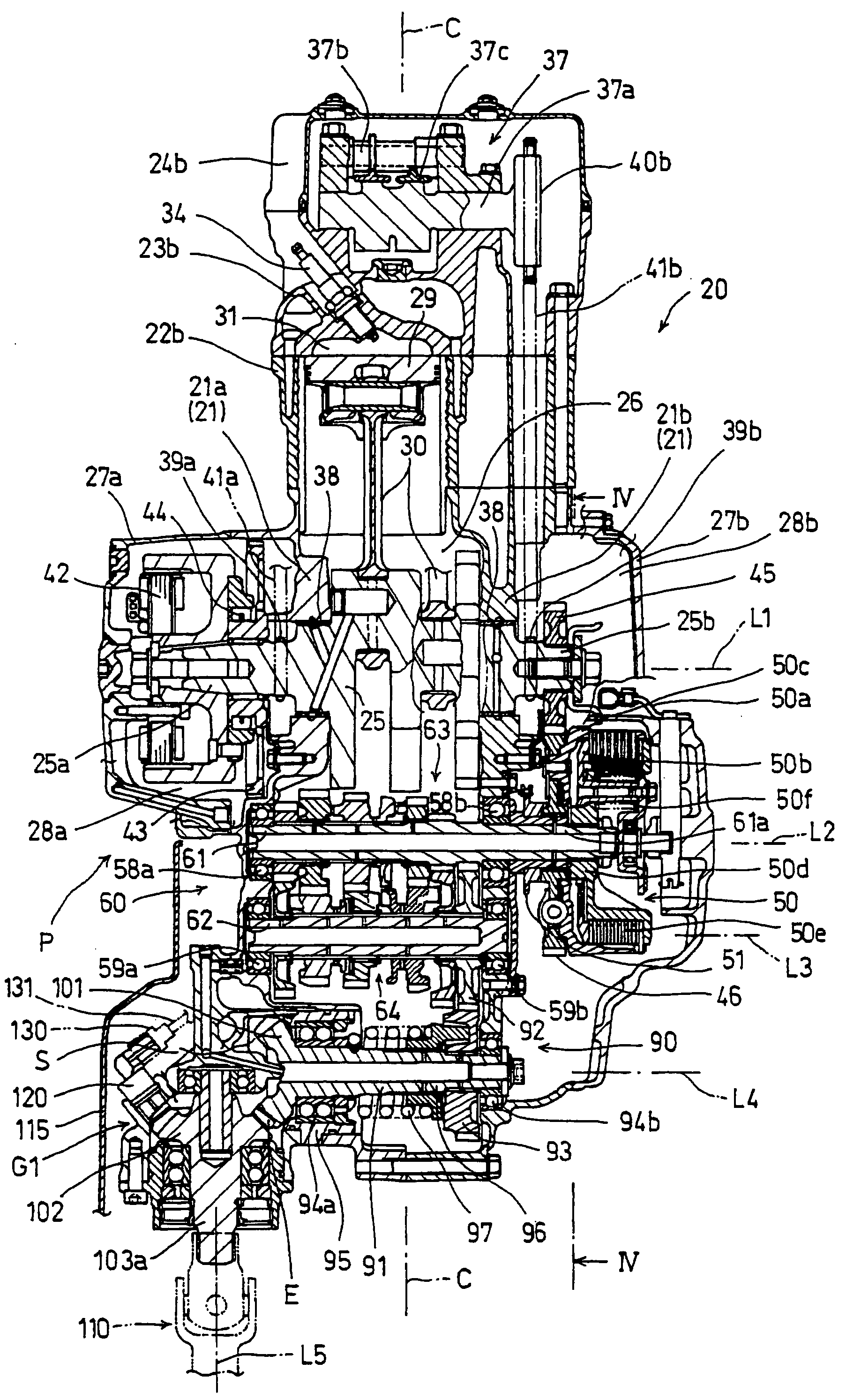
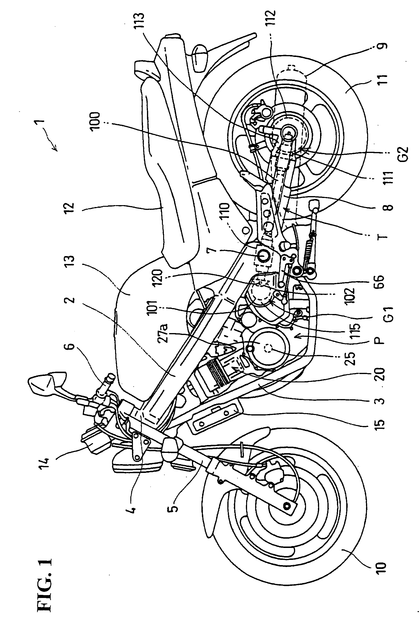
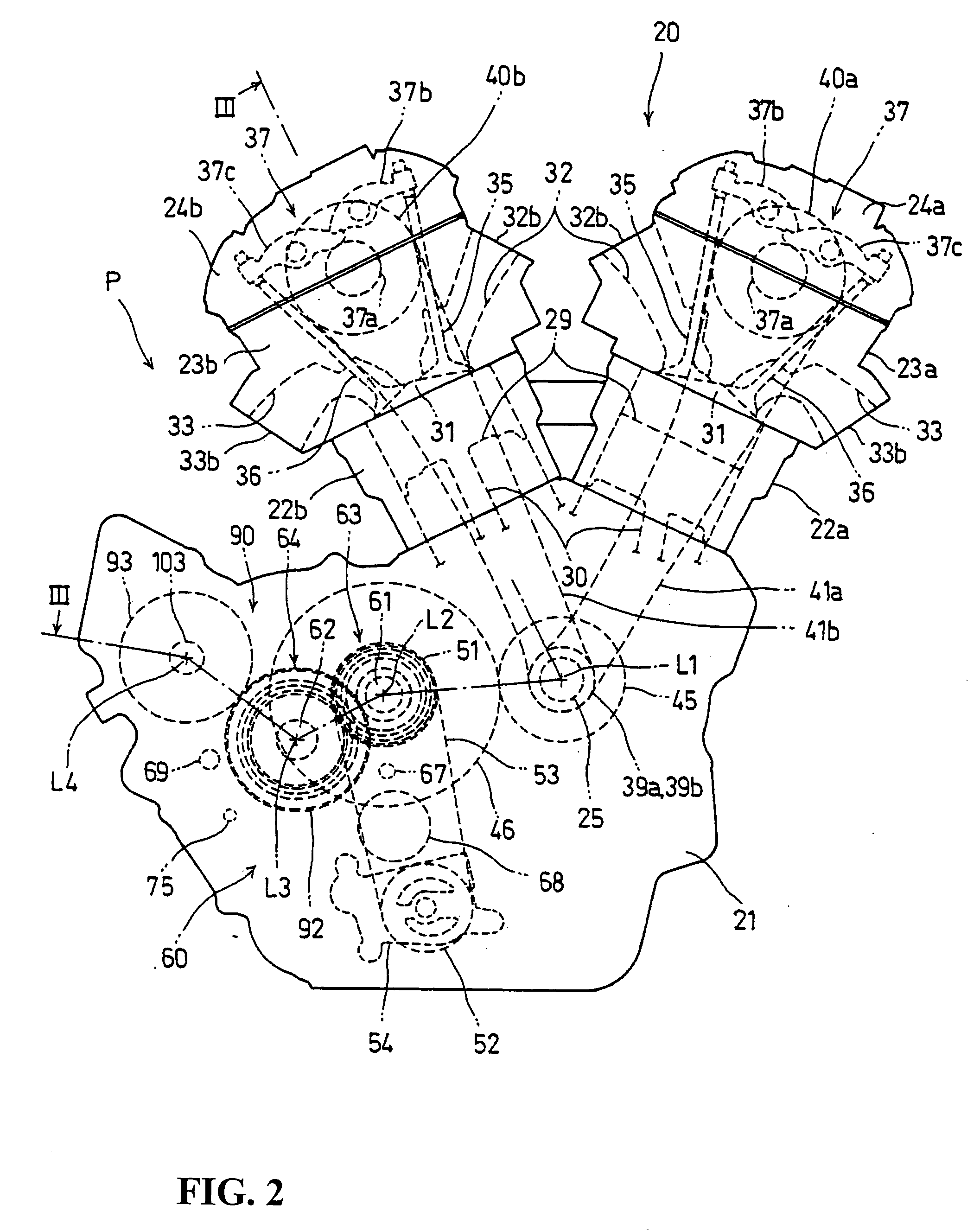
[0030] Referring to FIG. 1, a motorcycle 1 to which the present invention is applied includes a vehicle body frame having a left-right pair of main frames 2 and a left-right pair of under frames 3 disposed on the lower side of the main frames 2. A steering handle 6 is fixed to an upper end portion of a front fork 5 that is connected to a steering shaft rotatably supported on a head pipe 4 connected to front end portions of the main frames 2 and the under frames 3. A front wheel 10 is rotatably supported by lower end portions of the front fork 5. A power unit P is supported by the main frames 2 and the under frames 3. A swing arm 8 is swingably supported, at its left-right pair of front end portions, on pivot shafts 7 provided at rear end portions of the left and right main frames 2 with a rear wheel 11 rotatably supported on a rear end portion of the swing arm 8.

[0031] Further, the...


PUM


Abstract

A versatile vehicle speed sensor compactly disposed on the outside in a radial direction of a gear. A motorcycle includes a power unit having a torque take-out shaft for outputting a torque generated by an internal combustion engine as a drive torque for driving a rear wheel, a torque transmission mechanism T which includes a gear pair consisting of bevel gears and a drive shaft and which transmits the drive torque to the rear wheel, and a vehicle speed sensor such that teeth of a driven gear constituting the gear pair constitute a portion to be detected. The vehicle speed sensor includes a main body portion having a detecting portion opposed to the addendum of the teeth in the direction of a normal to the addendum cone surface of the driven gear, and the main body portion extends along the normal direction.

Description

CROSS-REFERENCE TO RELATED APPLICATIONS [0001] The present application claims priority under 35 USC 119 to Japanese Patent Application No. 2004-120815 filed on Apr. 15, 2004 the entire contents of which are hereby incorporated by reference. BACKGROUND OF THE INVENTION [0002] 1. Field of the Invention [0003] The present invention relates to a motorcycle comprising a vehicle speed sensor such that the teeth of a gear constituting a torque transmission mechanism for transmitting a drive torque from a power unit to a drive wheel constitute a portion to be detected. [0004] 2. Description Background Art [0005] In the motorcycle disclosed in Japanese Patent No. 3209663, a sensor constituting a rear wheel rotational speed device is mounted to a gear case connected to the rear end of a rear fork, and the tip end of the sensor is formed slantly along the tooth surface of a first rear gear of a rear-side bevel gear. This ensures that it is unnecessary to provide a multiple-toothed rotor separa...

Claims


Application Information

Patent Timeline
Patent Type & Authority Applications(United States)
IPC IPC(8): B62J99/00G01P1/02G01P3/488
CPCF02B61/02G01P3/488G01P1/026
Inventor OKANO, SHIGETAROMATSUO, KENJIINUI, HIROATSU
Owner HONDA MOTOR CO LTD
Why Eureka
Try Eureka