Apparatus for cutting concrete using abrasive cable

a technology of abrasive cable and concrete, which is applied in the direction of ceramic shaping apparatus, stone-like material working tools, manufacturing tools, etc., can solve the problems of inability to use in all states, inability to meet the needs of construction, and prior art devices experience undesirable and sometimes unpredictable changes in operation, precision and performance, etc., to achieve greater flexibility, reduce the effect of concrete slab spalling or chipping, and reduce the effect of labor intensity

Inactive Publication Date: 2005-10-20
VANGUNDY JEFFERY R
View PDF38 Cites 6 Cited by
  • Summary
  • Abstract
  • Description
  • Claims
  • Application Information

AI Technical Summary

Benefits of technology

[0014] The foot structure minimizes spalling or chipping of the concrete slab during cutting. This is accomplished by a channel-shaped foot having two horizontally-extending flanges which, during cutting, contact the surface of the concrete slab on each side of the cutting element. The foot structure retracts to maintain pressure on the surface of the concrete slab as the cutting element cuts into it.
[0015] The drive motor drives the drive pulley and the cutting element. The support carriage movably supports the cutting head and the motor on inboard legs and wheels and outboard legs and wheels that allow for rolling movement of the cutting head over and along the concrete slab while supporting the apparatus on the ground adjacent the concrete slab. The carriage also allows for lowering and raising the cutting element to engage and disengage the concrete slab during cutting.
[0016] Thus, it will be appreciated that the apparatus of the present invention provides a number of distinct advantages over the prior art, including, for example, that it works with all methods and procedures of cutting (e.g., early entry, dry green concrete, wet green concrete). Furthermore, the apparatus will work in any adverse weather conditions and temperatures and with any aggregate mix. Additionally, the apparatus has greater cutting ability to allow for greater flexibility with regard to when cuts can be made during the curing process. The apparatus also enables cutting to be performed without otherwise touching, walking upon, or disturbing the uncured concrete slab. Additionally, the apparatus automatically produces precise and accurate cuts that are both straight and uniformly deep, which, in turn, allows for easier and more efficient installation of joint-sealing material. Relatedly, the maximum depth of cut attainable by the apparatus is limited only by the degree of travel allowed for by the foot structure relative to the cutting element. The apparatus also operates to augur or push all concrete dust debris resulting from cutting out to the edges of the concrete slab, thereby providing, without additional cleaning steps, a cleaner surface to which the sealing material can bond. Thus, the apparatus of the present invention can result in substantial cost savings due to significant reductions in labor required to cut, clean, and seal large concrete slabs.

Problems solved by technology

Unfortunately, these prior art devices suffer from a number of problems and disadvantages including, for example, that they cannot be used in all states because of varying state specifications and procedures.
Furthermore, prior art devices experience undesirable and sometimes unpredictable changes in operation, including variations in precision and performance, when operating during adverse weather conditions, particularly relatively hot or cold ambient temperatures, or when cutting concrete slabs containing certain aggregate mixes.
Additionally, prior art devices have relatively limited power and cutting ability and therefore have a relatively narrow window of opportunity for cutting concrete slabs during the curing process.
Additionally, prior art devices are dependent on the workman's senses for accuracy, and therefore rarely produce cuts of uniform straightness and depth.
It is known in the prior art to create chalk lines on the surface of the concrete slabs for the workmen to follow when cutting, but creating these lines slows the cutting process, and the lines do not assist in establishing or determining cut depth.
Relatedly, because the prior art devices use abrasive disks as cutting elements, the maximum depth that can be cut is, in each instance, limited by the radius of the disk.
Prior art devices are also prone to leaving a substantial amount of concrete dust debris or other debris within the cut, which must then, in a separate step, be removed prior to filling the joint with sealing material.
If the debris is not adequately removed, particularly from the sides of the cut, then the sealing material may not bond.

Method used


Image

  • Apparatus for cutting concrete using abrasive cable
  • Apparatus for cutting concrete using abrasive cable
  • Apparatus for cutting concrete using abrasive cable

Examples


Embodiment Construction

.

BRIEF DESCRIPTION OF THE DRAWINGS

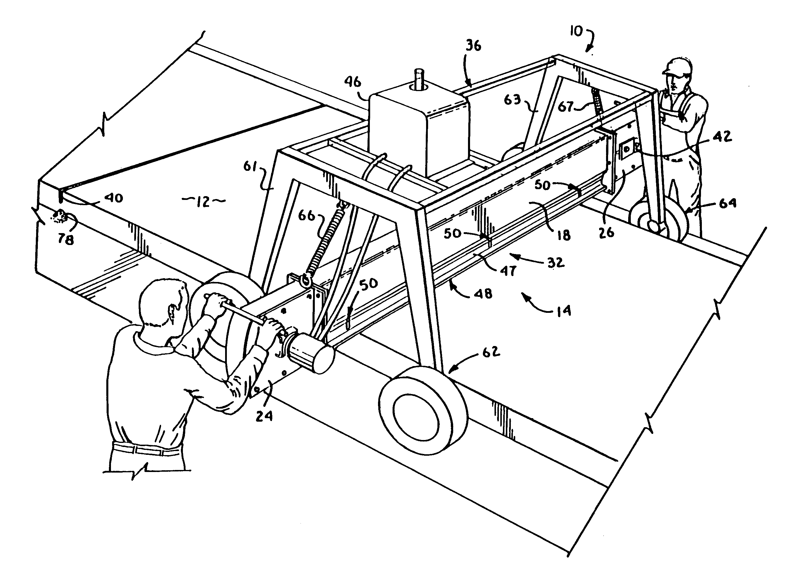
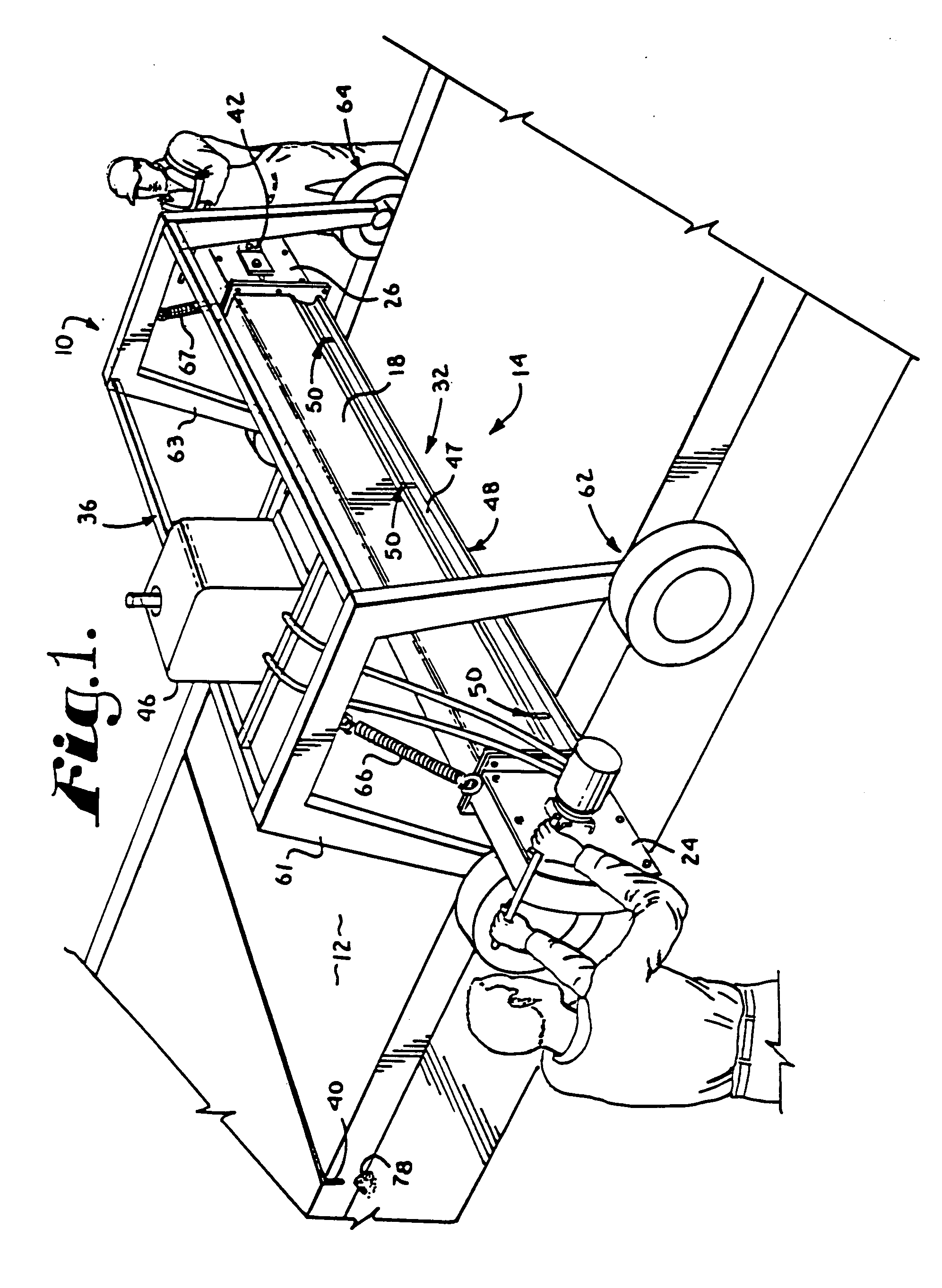
[0018]FIG. 1 is an isometric view of a preferred embodiment of the apparatus of the present invention, wherein the apparatus is depicted in actual operation.

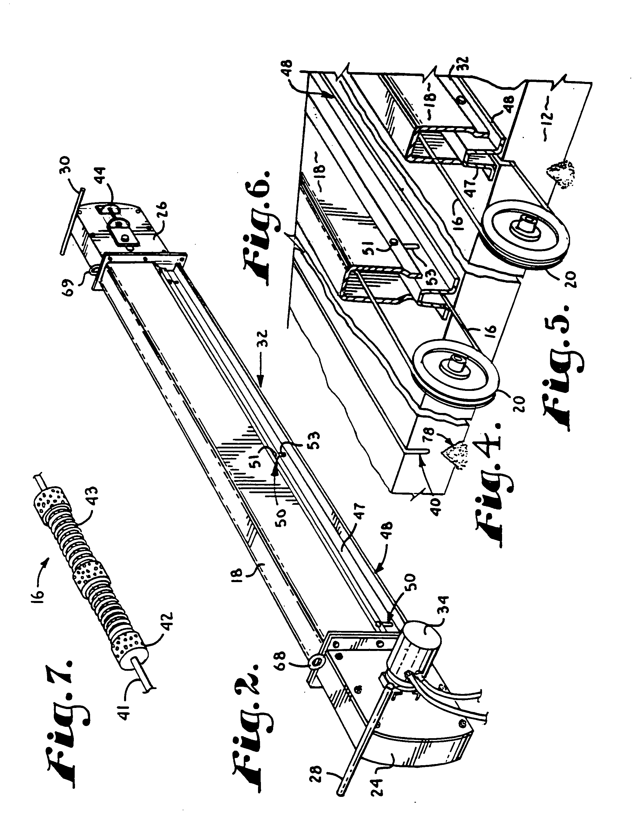
[0019]FIG. 2 is an isometric view of a cutting head component of the apparatus of FIG. 1.

[0020]FIG. 3 is an exploded, fragmentary, isometric view of certain subcomponents of the cutting head component of FIG. 2.

[0021]FIG. 4 is a sectional, fragmentary, isometric view of a portion of the apparatus of FIG. 1 immediately prior to beginning a cut.

[0022]FIG. 5 is a sectional, fragmentary, isometric view of the portion of the apparatus shown in FIG. 4 in the process of making the cut.

[0023]FIG. 6 is an isometric view of the finished cut which was begun in FIG. 4.

[0024]FIG. 7 is an enlarged, fragmentary, isometric view of a length of an abrasive cable in the form of diamond wire used as the preferred cutting element of the apparatus.

[0025]FIG. 8 is an enlarged and fragmentary cross-sectional vi...


PUM

PropertyMeasurementUnit
distanceaaaaaaaaaa
pressureaaaaaaaaaa
flexibleaaaaaaaaaa

Abstract

An apparatus for cutting large horizontal slabs of green or uncured concrete, such as roadways, with a single downward motion. The apparatus broadly comprises a cutting head including a cutting element, a drive pulley, an outboard pulley, and a foot structure; a drive motor; and a moveable support carriage. The cutting element is a closed loop of diamond wire entrained about the drive and outboard pulleys, with the drive pulley being driven by the drive motor. The foot structure includes a channel-shaped foot structure having two horizontally-extending flanges that function to minimizes spalling or chipping during cutting. The carriage movably supports the cutting head and the motor on inboard and outboard rolling elements, such as wheels or tracks, that allow for rolling movement over and along the concrete slab. The carriage also allows for lowering and raising the cutting element to engage and disengage the concrete slab during cutting.

Description

BACKGROUND OF THE INVENTION [0001] 1. Field of the Invention [0002] The present invention relates to devices and apparatuses for cutting large horizontal concrete slabs. More particularly, the present invention relates to an apparatus for cutting joints in roadways using an abrasive cable such as diamond wire. [0003] 2. Description of the Related Art [0004] It is often necessary or desirable to cut large slabs of concrete, such as, for example, to create transverse joints in roadways in order to control cracking due to expansion and contraction, settling, or other movement of the concrete slab. Once cut, these joints are filled with a sealing compound to prevent entry of water, oil, or other fluids that might otherwise adversely affect the integrity the concrete slab. A variety of prior art devices are known for making such cuts, all of which employ rotating abrasive disks as cutting elements. [0005] Unfortunately, these prior art devices suffer from a number of problems and disadva...

Claims


Application Information

Patent Timeline
Patent Type & Authority Applications(United States)
IPC IPC(8): B28B11/14B28D1/04B28D1/08
CPCB28D1/08B28B11/14
Inventor VANGUNDY, JEFFERY R.
Owner VANGUNDY JEFFERY R
Why Eureka
Try Eureka